RM38G0E _51 Engine / Hybrid System _101208 1GR-FE LUBRICATION _0470789 OIL LEVEL SENSOR A
1GR-FE LUBRICATION OIL LEVEL SENSOR INSTALLATION
CAUTION / NOTICE / HINT
COMPONENTS (INSTALLATION)
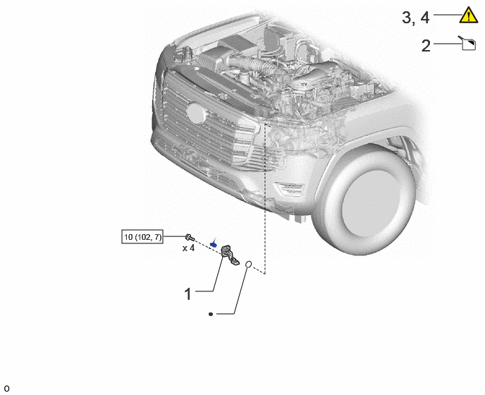
1.802,3.396 2.406,3.594 0.604,0.198 3.198,4.635 3.458,4.635 3.458,4.635 3.656,3.938 true 2.885,4.302 3.146,4.302 3.146,4.302 3.292,3.792 true 6.406,0.219 6.833,0.219 true 6.406,0.646 6.833,0.646 true 2.417,3.49 2.74,3.49 true 2.708,4.188 2.99,4.542 0.281,0.354 18 false 1 3.073,4.542 3.354,4.896 0.281,0.354 10 false ● 6.229,0.521 6.51,0.875 0.281,0.354 18 false 2 5.938,0.104 6.438,0.427 0.5,0.323 18 false 3, 4 1.833,3.427 2.469,3.719 0.635,0.292 8 false 10 (102, 7) 2.698,3.573 3.031,3.844 0.333,0.271 10 false x 4
| Procedure | Part Name Code |

|

|

|
|
|---|---|---|---|---|---|
| 1 | ENGINE OIL LEVEL SENSOR | 89491 | - | - | - |
| 2 | ADD ENGINE OIL | - | - | ( ) |
- |
| 3 | INSPECT ENGINE OIL LEVEL | - | () |
- | - |
| 4 | INSPECT FOR OIL LEAK | - | () |
- | - |

|
N*m (kgf*cm, ft.*lbf): Specified torque | ● | Non-reusable part |
3.198,2.99 3.896,3.198 0.698,0.208 5.375,2.792 6.073,3 0.698,0.208 1.958,2.458 1.958,2.938 false 0.875,1.448 1,1.01 1,1.01 1.208,1.01 false 3.729,2.219 3.729,2.688 3.729,2.688 3.906,2.688 false 5.698,1.781 5.698,2.25 false 3.188,3.094 2.958,3.094 2.958,3.094 2.958,2.406 false 6.083,2.885 6.26,2.885 6.26,2.885 6.26,2.198 false 1.667,2.719 1.927,2.906 0.26,0.188 10 false x 2 3.979,2.563 4.25,2.906 0.271,0.344 18 false 6 5.646,2.281 5.917,2.625 0.271,0.344 18 false 5 6.365,2.052 6.594,2.24 0.229,0.188 10 false x 2 1.26,0.927 1.49,1.115 0.229,0.188 10 false *2 3.063,2.302 3.292,2.49 0.229,0.188 10 false x 5 1.896,2.969 2.125,3.156 0.229,0.188 10 false *1 0.938,2.104 1.24,2.292 0.302,0.188 10 false x 2 3.25,3.021 4.01,3.281 0.76,0.26 8 false 29 (296, 21) 5.427,2.823 6.188,3.083 0.76,0.26 8 false 29 (296, 21)
| Procedure | Part Name Code |
|
|
|
|
|---|---|---|---|---|---|
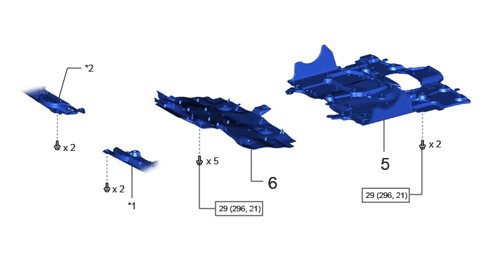
| 5 | NO. 2 ENGINE UNDER COVER ASSEMBLY | 51420 | - | - | - |
| 6 | NO. 1 ENGINE UNDER COVER ASSEMBLY | 51410 | - | - | - |
| *1 | ENGINE SIDE COVER SUB-ASSEMBLY LH | *2 | ENGINE SIDE COVER SUB-ASSEMBLY RH |
|
|
N*m (kgf*cm, ft.*lbf): Specified torque | - | - |
PROCEDURE

 89491 1.INSTALL ENGINE OIL LEVEL SENSOR
- Torque:
- 10 N*m (102 kgf*cm, 7 ft.*lbf)
2.ADD ENGINE OIL
3.INSPECT ENGINE OIL LEVEL
4.INSPECT FOR OIL LEAK
51420 5.INSTALL NO. 2 ENGINE UNDER COVER ASSEMBLY
51410 6.INSTALL NO. 1 ENGINE UNDER COVER ASSEMBLY
a.
3.792,2.521 4.042,2.844 0.25,0.323 18 false iii 0.229,2.542 0.479,2.865 0.25,0.323 18 false ii 0.302,0.083 0.552,0.406 0.25,0.323 18 false i

|
Bolt A |

|
Bolt B |

|
Install in this Direction | - | - |
i.
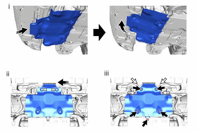
After attaching the 2 temporary holding guides of the No. 1 engine under cover assembly to the vehicle frame, set the No. 1 engine under cover assembly to the vehicle side while pulling the engine side cover sub-assembly RH and engine side cover sub-assembly LH as shown in the illustration.
ii.
Move the side of No. 1 engine under cover assembly facing the front of the vehicle and attach the 2 temporary holding guides to the vehicle frame.
iii.
Install the 5 bolts (A) and 4 bolts (B).
- Torque:
- for bolt (A) : 29 N*m (296 kgf*cm, 21 ft.*lbf)