V35A-FTS FUEL FUEL MAIN VALVE(for Double Tank Type) INSTALLATION
CAUTION / NOTICE / HINT
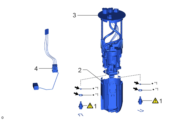
| Procedure | Part Name Code |

|

|

|
|
|---|---|---|---|---|---|
| 1 | FUEL MAIN VALVE ASSEMBLY | 23070 | ( ) |
- | - |
| 2 | NO. 1 FUEL SUB-TANK | 77131C | - | - | - |
| 3 | FUEL SUCTION PLATE SUB-ASSEMBLY | 77024A | - | - | - |
| 4 | FUEL SENDER GAUGE ASSEMBLY | 83320 | - | - | - |
| *1 | O-RING | - | - |
| ● | Non-reusable part |

|
Gasoline |
| Procedure | Part Name Code |
|
|
|
|
|---|---|---|---|---|---|
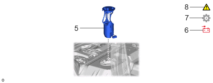
| 5 | FUEL SUCTION WITH PUMP AND GAUGE TUBE ASSEMBLY | 77020 | - | - | - |
| 6 | CONNECT CABLE TO NEGATIVE BATTERY TERMINAL | - | - | - | - |
| 7 | INITIALIZATION AFTER RECONNECTING BATTERY TERMINAL | - | - | - | () |
| 8 | INSPECT FOR FUEL LEAK | - | () |
- | - |
PROCEDURE

 23070 1.INSTALL FUEL MAIN VALVE ASSEMBLY
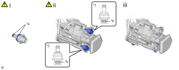
| *1 | Fuel Main Valve Assembly (for Low Pressure) | *2 | Fuel Main Valve Assembly (for High Pressure) |
| *a | Apply gasoline | *b | Identification Mark (Part Number) |
Install 4 new O-rings to the 2 fuel main valve assemblies.
- NOTICE:
-
When installing the O-rings, make sure they do not become pinched or cut.
Install the 2 fuel main valve assemblies to the fuel suction plate sub-assembly.
- NOTICE:
-
The fuel main valve assembly (for Low Pressure) and fuel main valve assembly (for High Pressure) have identification marks (part numbers). If the parts are installed in the wrong location, the engine may stall. Therefore, make sure to install the parts in the correct location.
- HINT:
-
Fuel Main Valve Assembly (for Low Pressure) 23070-31*** Fuel Main Valve Assembly (for High Pressure) 23070-36***
Install the 2 clips to the fuel suction plate sub-assembly.
77131C 2.INSTALL NO. 1 FUEL SUB-TANK
77024A 3.INSTALL FUEL SUCTION PLATE SUB-ASSEMBLY
83320 4.INSTALL FUEL SENDER GAUGE ASSEMBLY
77020A 5.INSTALL FUEL SUCTION WITH PUMP AND GAUGE TUBE ASSEMBLY
6.CONNECT CABLE TO NEGATIVE BATTERY TERMINAL
7. INITIALIZATION AFTER RECONNECTING BATTERY TERMINAL
Click hereGeneral>SETUP>WHEN DISCONNECTING OR RECONNECTING BATTERY TERMINAL>WORK PROCEDURE
- HINT:
-
When disconnecting and reconnecting the battery, there is an automatic learning function that completes learning when the respective system is used.
-
Click hereGeneral>SETUP>WHEN DISCONNECTING OR RECONNECTING BATTERY TERMINAL>AUTOMATIC LEARNING CHART
8.INSPECT FOR FUEL LEAK