F33A-FTV ENGINE CONTROL ECD SYSTEM(w/ DPF) P23AA72 Turbocharger/Supercharger Bypass Valve "A" Actuator Stuck Open
DESCRIPTION
Refer to DTC P003312.
Click hereEngine / Hybrid System>F33A-FTV (ENGINE CONTROL)>ECD SYSTEM (w/ DPF)>P003312
| DTC No. | Detection Item | DTC Detection Condition | Trouble Area | MIL | Note |
|---|---|---|---|---|---|
| P23AA72 | Turbocharger/Supercharger Bypass Valve "A" Actuator Stuck Open | During twin turbo operation, an intake air temperature sensor (for intercooler inlet) or intake air temperature sensor (for intercooler outlet) temperature of 190°C or more continues for 5.5 seconds or more. (1 trip detection logic) |
·
Air by-pass valve assembly
·
Intake air temperature sensor (for intercooler outlet)
·
Intake air temperature sensor (for intercooler inlet) |
Comes on | SAE Code: P23AA |
| DTC No. | Data List |
|---|---|
| P23AA72 |
·
Intake Air Temperature B1S1 (Turbo)
·
Intake Air Temperature B1S2
·
Air Bypass Valve Current-Carrying Request |
WIRING DIAGRAM
Refer to DTC P003312.
Click hereEngine / Hybrid System>F33A-FTV (ENGINE CONTROL)>ECD SYSTEM (w/ DPF)>P003312
CONFIRMATION DRIVING PATTERN
| DTC No. | DTC Detection Drive Pattern |
|---|---|
| P23AA72 |
·
Turn Active Test "Activate the Air Bypass Valve" ON and OFF, and check that the air bypass valve makes an operating sound.
·
Check the Data List item after using the GTS to perform the Active Test "Activate the 2 Stage VN Turbo" for approximately 30 seconds. |
PERFORM ACTIVE TEST "ACTIVATE THE 2 STAGE VN TURBO" AND CHECK DATA LIST
Use the GTS to perform the Active Test "Activate the 2 Stage VN Turbo", and use the snapshot function to record data for approximately 30 seconds after starting.
- Powertrain > Engine > Active Test
-
Active Test Display Activate the 2 Stage VN Turbo -
Data List Display Vehicle Speed Mass Air Flow Sensor Intake Manifold Absolute Pressure 1st Turbocharger/Supercharger Outlet Pressure (Control Value) 2nd Turbocharger/Supercharger Outlet Pressure (Control Value) Air Bypass Valve Current-Carrying Request Air Control Valve Current-Carrying Request Exhaust Control Valve Current-Carrying Request - 50004 372 42038 212,215,385,1459,1460,1462,1463,1461
- HINT:
-
·
Changes in data will be too extreme if there are many Data List items. Use a custom list to select only the required items.
·The operation of each control valve is completed after approximately 30 seconds.
Display the recorded data as a graph and check the value at the specified point.
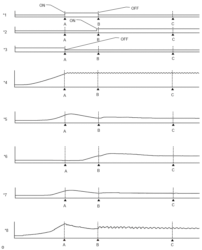
| *1 | Air Bypass Valve Current-Carrying Request | *2 | Air Control Valve Current-Carrying Request |
| *3 | Exhaust Control Valve Current-Carrying Request | *4 | Engine Speed |
| *5 | 1st Turbocharger/Supercharger Outlet Pressure (Control Value) | *6 | 2nd Turbocharger/Supercharger Outlet Pressure (Control Value) |
| *7 | Intake Manifold Absolute Pressure | *8 | Mass Air Flow Sensor |
- HINT:
-
Data from the illustration is for reference only and is retrieved in the following measurement environment.
-
Coolant Temperature: 88°C
Ambient Temperature: 25°C
Atmospheric Pressure: 101.3 kPa
- Result:
-
Check Point Normal Condition Diagnostic Note Illustration A: "Air Bypass Valve Current-Carrying Request" is ON and "Exhaust Control Valve Current-Carrying Request" is OFF 2nd turbocharger/supercharger outlet pressure (control value) is 88.3 to 114.3 kPa 2nd turbocharger/supercharger outlet pressure (control value) must not be too high during single turbo Illustration B: "Air Bypass Valve Current-Carrying Request" is OFF 2nd turbocharger/supercharger outlet pressure (control value) is 116.5 to 143.5 kPa Displays 2nd turbocharger/supercharger outlet pressure (control value) when switching from single turbo to twin turbo during the Active Test. Illustration C: The point where the change in pressure has stabilized after "Air Bypass Valve Current-Carrying Request" turns OFF The difference between 1st turbocharger/supercharger outlet pressure (control value) and 2nd turbocharger/supercharger outlet pressure (control value) is within 13 kPa Check that there is no difference between 1st turbocharger/supercharger outlet pressure (control value) and 2nd turbocharger/supercharger outlet pressure (control value) during twin turbo, so that the air control valve is open.
CAUTION / NOTICE / HINT
- NOTICE:
-
·
Inspect the fuses for circuits related to this system before performing the following procedure.
·After replacing the ECM, the new ECM needs registration (Click here Engine / Hybrid System>F33A-FTV (ENGINE CONTROL)>ECD SYSTEM (w/ DPF)>REGISTRATION) and initialization (Click here Engine / Hybrid System>F33A-FTV (ENGINE CONTROL)>ECD SYSTEM (w/ DPF)>INITIALIZATION).
·After replacing the ECM and performing "LEARNING VALUES WRITE", select "PM Regenerate Mode" using Utility of the GTS to perform PM forced regeneration.
Click hereEngine / Hybrid System>F33A-FTV (EMISSION CONTROL)>EMISSION CONTROL SYSTEM>ON-VEHICLE INSPECTION
- HINT:
-
Read Freeze Frame Data using the GTS. The ECM records vehicle and driving condition information as Freeze Frame Data the moment a DTC is stored. When troubleshooting, Freeze Frame Data can help determine if the vehicle was moving or stationary, if the engine was warmed up or not, if the air fuel ratio was lean or rich, and other data from the time the malfunction occurred.
PROCEDURE
Read the DTCs.
- Powertrain > Engine > Trouble Codes
- 50001 372
- Result:
-
Result Proceed to DTC P23AA72 is output A DTC P23AA72 and other DTCs are output B
- HINT:
-
If codes other than DTC P23AA72 are output, perform troubleshooting for those DTCs first.
A
B
Check that there are no malfunctions in intake/exhaust system piping such as damage, air suction or exhaust leaks in the engine room.
- Result:
-
Proceed to OK NG
OK
NG
Repair or replace the malfunctioning part in the intake/exhaust system.
Inspect the intake air temperature sensor (for intercooler inlet).
Click hereEngine / Hybrid System>F33A-FTV (ENGINE CONTROL)>INTAKE AIR TEMPERATURE SENSOR>INSPECTION
Inspect the intake air temperature sensor (for intercooler outlet).
Click hereEngine / Hybrid System>F33A-FTV (ENGINE CONTROL)>INTAKE AIR TEMPERATURE SENSOR>INSPECTION
- Result:
-
Proceed to OK NG
OK
NG
Enter the following menus: Powertrain / Engine / Active Test / Activate the Air Bypass Valve.
- Powertrain > Engine > Active Test
-
Tester Display Activate the Air Bypass Valve - 50004 372 42039 264,265
Turn the Active Test ON and OFF, and check that the air bypass valve makes an operating sound.
- HINT:
-
·
When turning the air bypass valve from ON to OFF, the valve makes a sitting sound.
·If it is difficult to distinguish the operating sound, repeat the Active Test and check again.
- Result:
-
Result Proceed to There is an operating sound A There is no operating sound B
A
B
Clear the DTCs.
- Powertrain > Engine > Clear DTCs
- 50002 372
- Result:
-
Proceed to NEXT
Turn the ignition switch off and wait for at least 30 seconds.
NEXT
Enter the following menus: Powertrain / Engine / Active Test / Activate the Air Bypass Valve.
- Powertrain > Engine > Active Test
-
Tester Display Activate the Air Bypass Valve - 50004 372 42039 264,265
Turn the Active Test ON and OFF, and check that the air bypass valve makes an operating sound.
- HINT:
-
·
When turning the air bypass valve from ON to OFF, the valve makes a sitting sound.
·If it is difficult to distinguish the operating sound, repeat the Active Test and check again.
Enter the following menus: Powertrain / Engine / Active Test / Activate the 2 Stage VN Turbo.
- Powertrain > Engine > Active Test
-
Tester Display Activate the 2 Stage VN Turbo - 50004 372 42038
Check the Data List item after performing the Active Test for approximately 30 seconds.
- HINT:
-
Refer to "CONFIRMATION DRIVING PATTERN"
Check that no DTCs are output.
- Powertrain > Engine > Trouble Codes
- 50001 372
- Result:
-
Proceed to NEXT
NEXT
Inspect the air by-pass valve assembly.
Click hereEngine / Hybrid System>F33A-FTV (INTAKE / EXHAUST)>TURBOCHARGER>INSPECTION
- Result:
-
Proceed to OK NG
OK
NG
Replace the intake air temperature sensor (for intercooler inlet).
Click hereEngine / Hybrid System>F33A-FTV (ENGINE CONTROL)>INTAKE AIR TEMPERATURE SENSOR>REMOVAL
Replace the intake air temperature sensor (for intercooler outlet).
Click hereEngine / Hybrid System>F33A-FTV (ENGINE CONTROL)>INTAKE AIR TEMPERATURE SENSOR>REMOVAL
- Result:
-
Proceed to NEXT
NEXT