F33A-FTV INTAKE / EXHAUST TURBOCHARGER INSPECTION
CAUTION / NOTICE / HINT
- HINT:
-
Perform "Inspection After Repair" after replacing the turbocharger sub-assembly or No. 2 turbocharger sub-assembly.
-
·
PROCEDURE

 17201 1.VISUALLY CHECK TURBOCHARGER SUB-ASSEMBLY
Check for deformation and cracks in the compressor impeller on the intake side.
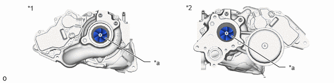
| *1 | Turbocharger Sub-assembly | *2 | No. 2 Turbocharger Sub-assembly |
| *a | Compressor Impeller | - | - |
If the compressor impeller is cracked or deformed, replace the turbocharger sub-assembly or No. 2 turbocharger sub-assembly.
Check for deformation and cracks in the turbine wheel on the exhaust side.
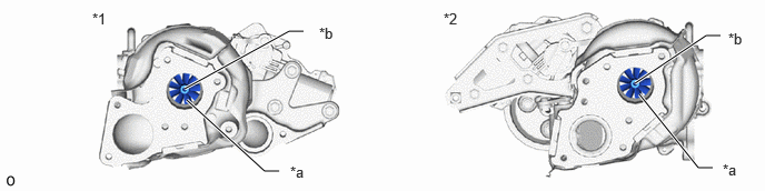
| *1 | Turbocharger Sub-assembly | *2 | No. 2 Turbocharger Sub-assembly |
| *a | Turbine Wheel | *b | Head of Turbine on Exhaust Side |
If the turbine wheel is cracked or deformed, replace the turbocharger sub-assembly or No. 2 turbocharger sub-assembly.
- NOTICE:
-
Even if there is wearing on the head of the turbine on the exhaust side, it does not cause any problems.
17201 2.INSPECT AXIAL PLAY OF TURBINE SHAFT
Using a dial indicator, insert the needle of the dial indicator into the exhaust side of the turbine shaft.
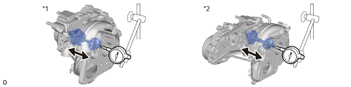
| *1 | Turbocharger Sub-assembly | *2 | No. 2 Turbocharger Sub-assembly |
- NOTICE:
-
Turbocharger sub-assembly, No. 2 turbocharger sub-assembly and dial indicators are surely fixed when performing measurement.
Move the turbine shaft in an axial direction and measure the axial play of the turbine shaft.
- Maximum axial play:
-
0.11 mm (0.00433 in.)
If the axial play is more than the maximum, replace the turbocharger sub-assembly or No. 2 turbocharger sub-assembly.
17201 3.CHECK TURBINE SHAFT ROTATION
Rotate the turbine wheel on the exhaust side with your finger and check that it rotates smoothly.
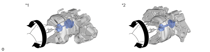
| *1 | Turbocharger Sub-assembly | *2 | No. 2 Turbocharger Sub-assembly |
- HINT:
-
Even if it takes a little effort to rotate the turbine wheel, this is not a problem.
If the turbine wheel does not rotate smoothly, replace the turbocharger sub-assembly or No. 2 turbocharger sub-assembly.
4.INSPECT TURBOCHARGER NOZZLE VANE CONTROL ACTUATOR
Remove the turbocharger nozzle vane control actuator.
Remove the intercooler assembly.
Click hereEngine / Hybrid System>F33A-FTV (INTAKE / EXHAUST)>INTERCOOLER>REMOVAL
Remove the intake air control valve assembly.
Click hereEngine / Hybrid System>F33A-FTV (INTAKE / EXHAUST)>INTAKE AIR CONTROL VALVE>REMOVAL
Remove the turbocharger nozzle vane control actuator.
Click hereEngine / Hybrid System>F33A-FTV (INTAKE / EXHAUST)>TURBOCHARGER>DISASSEMBLY
Remove the No. 2 turbocharger nozzle vane control actuator.
Remove the EGR cooler with electric EGR control valve assembly.
Click hereEngine / Hybrid System>F33A-FTV (EMISSION CONTROL)>EGR VALVE>REMOVAL
Remove the No. 2 turbocharger nozzle vane control actuator.
Click hereEngine / Hybrid System>F33A-FTV (INTAKE / EXHAUST)>TURBOCHARGER>DISASSEMBLY
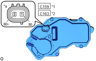
| *1 | Turbocharger Nozzle Vane Control Actuator |
| *2 | No. 2 Turbocharger Nozzle Vane Control Actuator |
| *a | Component without harness connected (Turbocharger Nozzle Vane Control Actuator) |
Measure the resistance according to the value(s) in the table below.
- Standard Resistance (Turbocharger Nozzle Vane Control Actuator):
-
Tester Connection Condition Specified Condition Click Location & Routing(C159)Location & Routingewd_type=routing;type=c;code=C159
C159-1 (M-) - C159-2 (M+) 20°C (68°F) 1 to 100 Ω
- Standard Resistance (No. 2 Turbocharger Nozzle Vane Control Actuator):
-
Tester Connection Condition Specified Condition Click Location & Routing(C163)Location & Routingewd_type=routing;type=c;code=C163
C163-1 (M-) - C163-2 (M+) 20°C (68°F) 1 to 100 Ω
- HINT:
-
The temperature indicated in "Condition" is the temperature of the turbocharger nozzle vane control actuator.
If the result is not as specified, replace the turbocharger nozzle vane control actuator.
Using a megohmmeter set to 500V, measure the resistance according to the table below.
- NOTICE:
-
Be sure to set the megohmmeter to 500 V when performing this check. Using a setting higher than 500 V can result in damage to the component being inspected.
- Standard Resistance (Turbocharger Nozzle Vane Control Actuator):
-
Tester Connection Condition Specified Condition Click Location & Routing(C159)Location & Routingewd_type=routing;type=c;code=C159
C159-1 (M-) - Body ground Always 10 MΩ or higher C159-2 (M+) - Body ground Always 10 MΩ or higher
- Standard Resistance (No. 2 Turbocharger Nozzle Vane Control Actuator):
-
Tester Connection Condition Specified Condition Click Location & Routing(C163)Location & Routingewd_type=routing;type=c;code=C163
C163-1 (M-) - Body ground Always 10 MΩ or higher C163-2 (M+) - Body ground Always 10 MΩ or higher
If the result is not as specified, replace the turbocharger nozzle vane control actuator.
Install the No. 2 turbocharger nozzle vane control actuator.
Install the No. 2 turbocharger nozzle vane control actuator.
Click hereEngine / Hybrid System>F33A-FTV (INTAKE / EXHAUST)>TURBOCHARGER>REASSEMBLY
Install the EGR cooler with electric EGR control valve assembly.
Click hereEngine / Hybrid System>F33A-FTV (EMISSION CONTROL)>EGR VALVE>INSTALLATION
Install the turbocharger nozzle vane control actuator.
Install the turbocharger nozzle vane control actuator.
Click hereEngine / Hybrid System>F33A-FTV (INTAKE / EXHAUST)>TURBOCHARGER>REASSEMBLY
Install the intake air control valve assembly.
Click hereEngine / Hybrid System>F33A-FTV (INTAKE / EXHAUST)>INTAKE AIR CONTROL VALVE>INSTALLATION
Install the intercooler assembly.
Click hereEngine / Hybrid System>F33A-FTV (INTAKE / EXHAUST)>INTERCOOLER>INSTALLATION
17670B 5.INSPECT AIR BY-PASS VALVE ASSEMBLY
Remove the air by-pass valve assembly.
Remove the inlet compressor elbow.
Remove the air by-pass valve assembly.
Click hereEngine / Hybrid System>F33A-FTV (INTAKE / EXHAUST)>TURBOCHARGER>DISASSEMBLY
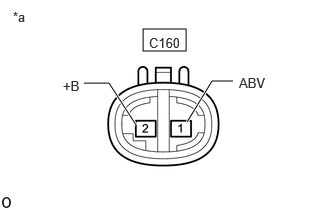
| *a | Component without harness connected (Air By-pass Valve Assembly) |
Measure the resistance according to the value(s) in the table below.
- Standard Resistance:
-
Tester Connection Condition Specified Condition Click Location & Routing(C160)Location & Routingewd_type=routing;type=c;code=C160
C160-1 (ABV) - C160-2 (+B) 20°C (68°F) 8.6 to 9.6 Ω
If the result is not as specified, replace the air by-pass valve assembly.
Check the operation of the air by-pass valve assembly.
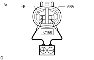
| *a | Component without harness connected (Air By-pass Valve Assembly) |
When applying battery voltage to the air by-pass valve assembly connector, check for an operating sound from the air by-pass valve assembly.
- NOTICE:
-
·
Inspect for a short time (10 seconds or less).
·Make sure to perform switching from the battery terminal side.
If the plunger does not make an operating sound, replace the air by-pass valve assembly.
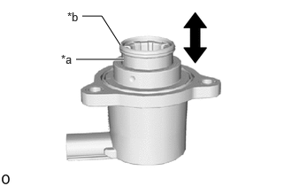
| *a | Plunger |
| *b | Seal Surface of Plunger |
When the plunger of the air by-pass valve assembly is pressed and released, check that the plunger quickly returns to its original position.
- NOTICE:
-
Make sure no foreign matter is stuck to the plunger seal of the air by-pass valve assembly and the plunger seal is not damaged.
If the plunger does not return to its original position, replace the air by-pass valve assembly.
Install the air by-pass valve assembly.
Install the air by-pass valve assembly.
Click hereEngine / Hybrid System>F33A-FTV (INTAKE / EXHAUST)>TURBOCHARGER>REASSEMBLY
Install the inlet compressor elbow.
Click hereGeneral>MAINTENANCE>F33A-FTV DRIVE BELT>INSTALLATION
6.INSPECT TURBOCHARGER ACTUATOR ASSEMBLY
Remove the turbocharger actuator assembly.
Remove the air cleaner assembly with air cleaner hose.
Click hereEngine / Hybrid System>F33A-FTV (INTAKE / EXHAUST)>VACUUM SWITCHING VALVE>REMOVAL
Remove the EGR cooler with electric EGR control valve assembly.
Click hereEngine / Hybrid System>F33A-FTV (EMISSION CONTROL)>EGR VALVE>REMOVAL
Remove the No. 2 turbocharger nozzle vane control actuator.
Click hereEngine / Hybrid System>F33A-FTV (INTAKE / EXHAUST)>TURBOCHARGER>DISASSEMBLY
Remove the water outlet.
Click hereEngine / Hybrid System>F33A-FTV (FUEL)>FUEL SUPPLY PUMP>REMOVAL
Remove the No. 2 turbocharger stay.
Click hereEngine / Hybrid System>F33A-FTV (FUEL)>FUEL INJECTOR>REMOVAL
Remove the turbocharger actuator assembly.
Click hereEngine / Hybrid System>F33A-FTV (INTAKE / EXHAUST)>TURBOCHARGER>DISASSEMBLY
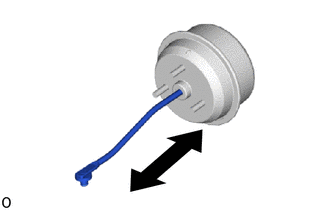
Check that the rod portion of the turbocharger actuator assembly smoothly returns to its original position when it is pressed in and released.
If the rod does not smoothly return, replace the turbocharger actuator assembly.
Install the turbocharger actuator assembly.
Install the turbocharger actuator assembly.
Click hereEngine / Hybrid System>F33A-FTV (INTAKE / EXHAUST)>TURBOCHARGER>REASSEMBLY
Install the No. 2 turbocharger stay.
Click hereEngine / Hybrid System>F33A-FTV (FUEL)>FUEL INJECTOR>INSTALLATION
Install the water outlet.
Click hereEngine / Hybrid System>F33A-FTV (FUEL)>FUEL SUPPLY PUMP>INSTALLATION
Install the No. 2 turbocharger nozzle vane control actuator.
Click hereEngine / Hybrid System>F33A-FTV (INTAKE / EXHAUST)>TURBOCHARGER>REASSEMBLY
Install the EGR cooler with electric EGR control valve assembly.
Click hereEngine / Hybrid System>F33A-FTV (EMISSION CONTROL)>EGR VALVE>INSTALLATION
Install the air cleaner assembly with air cleaner hose.
Click hereEngine / Hybrid System>F33A-FTV (INTAKE / EXHAUST)>VACUUM SWITCHING VALVE>INSTALLATION