F33A-FTV ENGINE MECHANICAL FRONT CRANKSHAFT OIL SEAL INSTALLATION
CAUTION / NOTICE / HINT
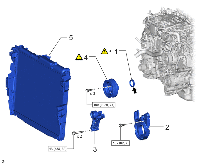
| Procedure | Part Name Code |

|

|

|
|
|---|---|---|---|---|---|
| 1 | TIMING CHAIN OR BELT COVER OIL SEAL | 11302A | ( ) |
- | - |
| 2 | NO. 2 TIMING CHAIN COVER INSULATOR | 11339D | - | - | - |
| 3 | V-RIBBED BELT TENSIONER ASSEMBLY | 16620D | - | - | - |
| 4 | CRANKSHAFT PULLEY SUB-ASSEMBLY | 13408 | () |
- | - |
| 5 | RADIATOR ASSEMBLY | 16400 | - | - | - |

|
N*m (kgf*cm, ft.*lbf): Specified torque | ● | Non-reusable part |

|
MP grease | - | - |
PROCEDURE

 11302A 1.INSTALL TIMING CHAIN OR BELT COVER OIL SEAL
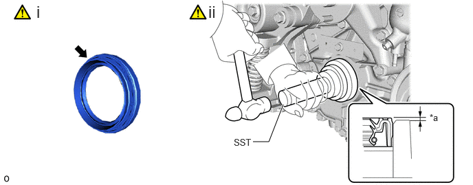
| *a | 0 to 2.0 mm (0 to 0.0787 in.) | - | - |
Apply MP grease to the lip of a new timing chain or belt cover oil seal.
Using SST, evenly tap in the timing chain or belt cover oil seal until its surface is flush with the end face of the timing chain or belt cover sub-assembly.
- SST
-
09316-12010
09950-70010 (09951-07100)
09950-60021 (09951-00890)
- Oil Seal Protrusion Height:
-
0 to 2.0 mm (0 to 0.0787 in.)
- NOTICE:
-
·
Make sure that the lip of the timing chain or belt cover oil seal. is properly installed.
·Do not tap the front crankshaft oil seal at an angle.
11339D 2.INSTALL NO. 2 TIMING CHAIN COVER INSULATOR
16620D 3.INSTALL V-RIBBED BELT TENSIONER ASSEMBLY
13408 4.INSTALL CRANKSHAFT PULLEY SUB-ASSEMBLY
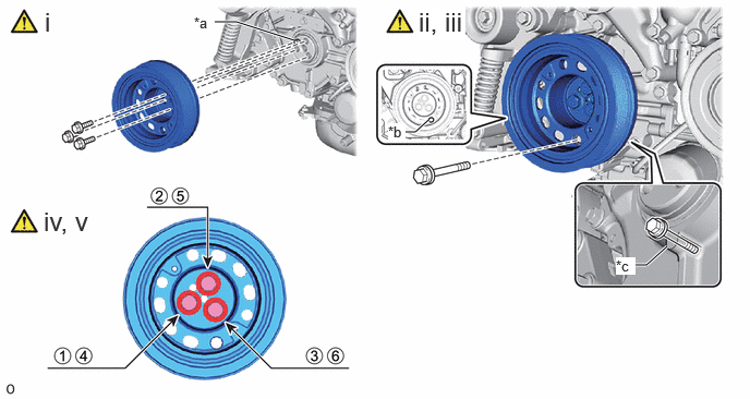
| *a | Knock Pin | *b | Service Hole |
| *c | Protrusion | - | - |
Align the crankshaft pulley sub-assembly and the crankshaft knock pin, and temporarily install the crankshaft pulley sub-assembly with the 3 bolts.
Align the service hole of the crankshaft pulley sub-assembly with the position as shown in the illustration.
Install a service bolt and fix the crankshaft pulley sub-assembly.
| Length | 120 mm (4.72 in.) or more |
| Diameter | 14 mm (0.551 in.) |
| Pitch | 1.5 |
| Thread Length | 70 mm (2.76 in.) or more |
- HINT:
-
The crankshaft pulley sub-assembly is fixed by hooking a service bolt on the convex part of the timing chain cover sub-assembly.
Uniformly tighten the 3 bolts in 2 passes in the order shown in the illustration.
- Torque:
- 100 N*m (1020 kgf*cm, 74 ft.*lbf)
Remove the service bolt.
16400 5.INSTALL RADIATOR ASSEMBLY