F33A-FTV EMISSION CONTROL EXHAUST GAS TEMPERATURE SENSOR(for DPF) INSTALLATION
CAUTION / NOTICE / HINT
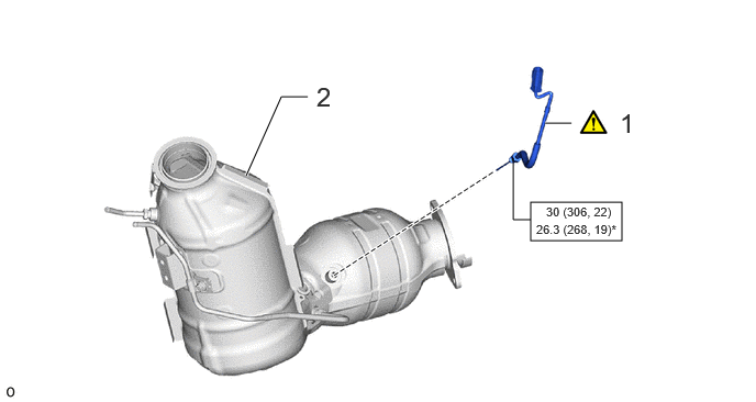
| Procedure | Part Name Code |

|

|

|
|
|---|---|---|---|---|---|
| 1 | NO. 3 EXHAUST GAS TEMPERATURE SENSOR | 89425B | ( ) |
- | - |
| 2 | FRONT EXHAUST PIPE ASSEMBLY | 17410 | - | - | - |

|
N*m (kgf*cm, ft.*lbf): Specified torque | * | For use with union nut wrench |
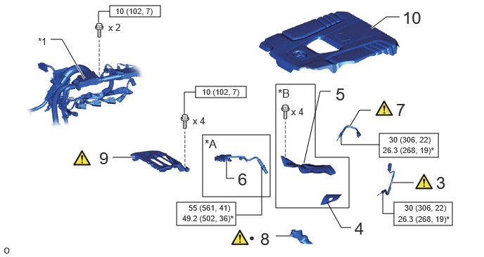
| Procedure | Part Name Code |
|
|
|
|
|---|---|---|---|---|---|
| 3 | NO. 2 EXHAUST GAS TEMPERATURE SENSOR | 89425A | - | - | - |
| 4 | NO. 3 EXHAUST MANIFOLD HEAT INSULATOR (w/o Urea SCR System) | 17619 | - | - | - |
| 5 | INTAKE PIPE INSULATOR (w/o Urea SCR System) | 17117A | - | - | - |
| 6 | NO. 1 NITROGEN OXIDES SENSOR (w/ Urea SCR System) | 89463C | - | - | - |
| 7 | EXHAUST GAS TEMPERATURE SENSOR | 89425 | - | - | |
| 8 | EXHAUST FUEL ADDITION INJECTOR HEAT INSULATOR | 23600G | - | - | |
| 9 | INTERCOOLER INSULATOR | 17951 | - | - | - |
| 10 | NO. 1 ENGINE COVER SUB-ASSEMBLY | 12601B | - | - | - |
| *A | w/ Urea SCR System | *B | w/o Urea SCR System |
| *1 | Engine wire | - | - |
|
|
N*m (kgf*cm, ft.*lbf): Specified torque | * | For use with union nut wrench |
| ● | Non-reusable part | - | - |
PROCEDURE

 89425B 1.INSTALL NO. 3 EXHAUST GAS TEMPERATURE SENSOR
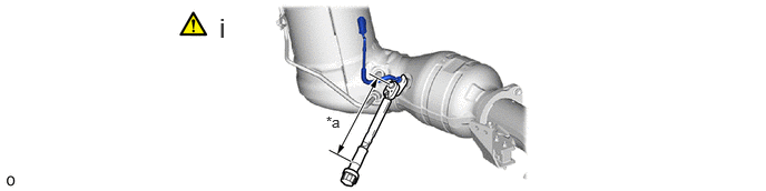
| *a | Torque Wrench Fulcrum Length | - | - |
Using a 14 mm union nut wrench, install the No. 3 exhaust gas temperature sensor to the front exhaust pipe assembly.
- Torque:
- Specified tightening torque:
-
30 N*m (306 kgf*cm, 22 ft.*lbf)
- NOTICE:
-
If the exhaust gas temperature sensor is dropped, replace it with a new one.
- HINT:
-
·
Calculate the torque wrench reading when changing the fulcrum length of the torque wrench.
Click hereGeneral>INTRODUCTION>REPAIR INSTRUCTION>PRECAUTION
·When using a union nut wrench (fulcrum length of 25 mm (0.984 in.)) + torque wrench (fulcrum length of 180 mm (7.09 in.)): 26.3 N*m (268 kgf*cm, 19 ft.*lbf)
17410 2.INSTALL FRONT EXHAUST PIPE ASSEMBLY
89425A 3.INSTALL NO. 2 EXHAUST GAS TEMPERATURE SENSOR
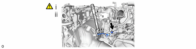
| *a | Torque Wrench Fulcrum Length | - | - |
Using a 14 mm union nut wrench, install the No. 2 exhaust gas temperature sensor.
- Torque:
- Specified tightening torque:
-
30 N*m (306 kgf*cm, 22 ft.*lbf)
- NOTICE:
-
If the exhaust gas temperature sensor is dropped, replace it with a new one.
- HINT:
-
·
Calculate the torque wrench reading when changing the fulcrum length of the torque wrench.
Click hereGeneral>INTRODUCTION>REPAIR INSTRUCTION>PRECAUTION
·When using a union nut wrench (fulcrum length of 25 mm (0.984 in.)) + torque wrench (fulcrum length of 180 mm (7.09 in.)): 26.3 N*m (268 kgf*cm, 19 ft.*lbf)
Attach the clamp and connect the exhaust gas temperature sensor connector.
17169 4.INSTALL NO. 3 EXHAUST MANIFOLD HEAT INSULATOR (w/o Urea SCR System)
17117A 5.INSTALL INTAKE PIPE INSULATOR (w/o Urea SCR System)
89463C 6.INSTALL NO. 1 NITROGEN OXIDES SENSOR (w/ Urea SCR System)
89425 7.INSTALL EXHAUST GAS TEMPERATURE SENSOR
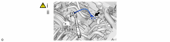
| *a | Torque Wrench Fulcrum Length | - | - |
Using a 14 mm union nut wrench, install the exhaust gas temperature sensor.
- Torque:
- Specified tightening torque:
-
30 N*m (306 kgf*cm, 22 ft.*lbf)
- NOTICE:
-
If the exhaust gas temperature sensor is dropped, replace it with a new one.
- HINT:
-
·
Calculate the torque wrench reading when changing the fulcrum length of the torque wrench.
Click hereGeneral>INTRODUCTION>REPAIR INSTRUCTION>PRECAUTION
·When using a union nut wrench (fulcrum length of 25 mm (0.984 in.)) + torque wrench (fulcrum length of 180 mm (7.09 in.)): 26.3 N*m (268 kgf*cm, 19 ft.*lbf)
Attach the clamp and connect the exhaust gas temperature sensor connector.
23600G 8.INSTALL EXHAUST FUEL ADDITION INJECTOR HEAT INSULATOR
17951 9.INSTALL INTERCOOLER INSULATOR
12601B 10.INSTALL NO. 1 ENGINE COVER SUB-ASSEMBLY