F33A-FTV EMISSION CONTROL MONOLITHIC CONVERTER(for Rear Side) INSTALLATION
CAUTION / NOTICE / HINT
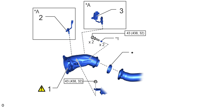
| Procedure | Part Name Code |

|

|

|
|
|---|---|---|---|---|---|
| 1 | NO. 2 FRONT EXHAUST PIPE SUB-ASSEMBLY | 17402 | ( ) |
- | - |
| 2 | NO. 4 EXHAUST GAS TEMPERATURE SENSOR | 89425C | - | - | - |
| 3 | NO. 2 NITROGEN OXIDES SENSOR | 89463D | - | - | - |
| *A | w/ Urea SCR System | - | - |
| *1 | Compression spring | - | - |

|
N*m (kgf*cm, ft.*lbf): Specified torque | - | - |
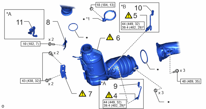
| Procedure | Part Name Code |
|
|
|
|
|---|---|---|---|---|---|
| 4 | NO. 3 EXHAUST GAS TEMPERATURE SENSOR | 89425B | () |
- | - |
| 5 | AIR FUEL RATIO SENSOR | 89467B | () |
- | - |
| 6 | FRONT EXHAUST PIPE SUB-ASSEMBLY | 17401 | () |
- | - |
| 7 | MANIFOLD STAY | 17118E | () |
- | - |
| 8 | EXHAUST PIPE HEAT INSULATOR | 17435 | - | - | - |
| 9 | NO. 3 EXHAUST GAS TEMPERATURE SENSOR CONNECTOR | 89425B | - | - | - |
| 10 | AIR FUEL RATIO SENSOR CONNECTOR | 89467B | - | - | - |
| 11 | DIFFERENTIAL PRESSURE SENSOR ASSEMBLY | - | - | - | - |
| *A | w/ DPF | *B | w/o Urea SCR System |
| *1 | Exhaust pipe clamp RH | - | - |
|
|
N*m (kgf*cm, ft.*lbf): Specified torque | * | for use with SST or union nut wrench |
| ● | Non-reusable part | - | - |
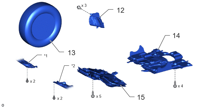
| Procedure | Part Name Code |
|
|
|
|
|---|---|---|---|---|---|
| 12 | FRONT FENDER APRON TRIM PACKING C | 53783 | - | - | - |
| 13 | FRONT WHEELS | - | - | - | - |
| 14 | NO. 2 ENGINE UNDER COVER ASSEMBLY | 51420 | - | - | - |
| 15 | NO. 1 ENGINE UNDER COVER ASSEMBLY | 51410 | - | - | - |
| *1 | ENGINE SIDE COVER SUB-ASSEMBLY RH | *2 | ENGINE SIDE COVER SUB-ASSEMBLY LH |
PROCEDURE

 17402 1.INSTALL NO. 2 FRONT EXHAUST PIPE SUB-ASSEMBLY
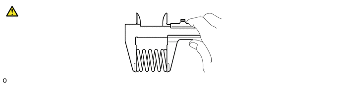
Measure the spring height.
- Standard:
-
43 mm (1.693 in.) or more
If the result is not as specified, replace the spring.
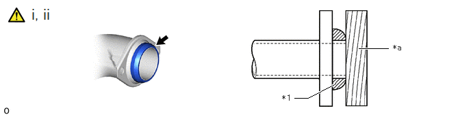
| *1 | Gasket | - | - |
| *a | Wooden Block | - | - |
Temporarily install a new gasket to the No. 2 Front exhaust pipe sub-assembly.
Using a plastic-faced hammer and wooden block, tap in the gasket until its surface is flush with the No. 2 Front exhaust pipe sub-assembly.
- NOTICE:
-
·
Be sure to install the gasket so that it faces the correct direction.
·Do not reuse the gasket.
·Do not damage the gasket.
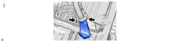
Connect the No. 2 Front exhaust pipe sub-assembly to the center exhaust pipe assembly with the 2 compression springs and 2 bolts.
- Torque:
- 43 N*m (438 kgf*cm, 32 ft.*lbf)
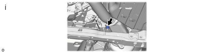
Install the No. 2 front exhaust pipe sub-assembly with the nut.
- Torque:
- 43 N*m (438 kgf*cm, 32 ft.*lbf)
89425C 2.INSTALL NO. 4 EXHAUST GAS TEMPERATURE SENSOR (w/ Urea SCR System)
89463D 3.INSTALL NO. 2 NITROGEN OXIDES SENSOR (w/ Urea SCR System)
89425B 4.INSTALL NO. 3 EXHAUST GAS TEMPERATURE SENSOR (w/ DPF)
|
|
Click here() |
89467B 5.INSTALL AIR FUEL RATIO SENSOR (w/o Urea SCR System)
|
|
Click here() |
17401 6.INSTALL FRONT EXHAUST PIPE SUB-ASSEMBLY
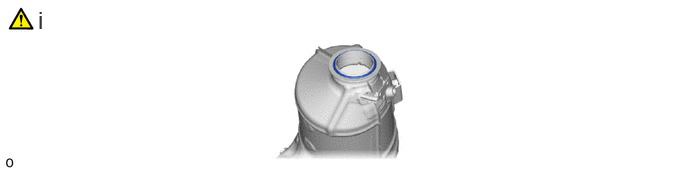
Set a new gasket to the front exhaust pipe sub-assembly.
- NOTICE:
-
When reusing the front exhaust pipe sub-assembly, clean the gasket groove and make sure no old gasket remains.
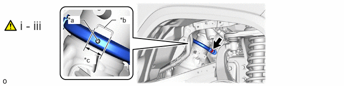
| *a | Exhaust Pipe Clamp RH Hole | *b | Exhaust Manifold Converter Sub-assembly Positioning Mark |
| *c | Position Alignment Range | - | - |
Set a new exhaust pipe clamp RH to the front exhaust pipe sub-assembly.
Align the clamp hole on the exhaust pipe clamp side within the positioning mark on the exhaust manifold converter sub-assembly side.
Tighten the nut.
- Torque:
- 18 N*m (184 kgf*cm, 13 ft.*lbf)
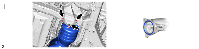
Install a new gasket and front exhaust pipe sub-assembly with the 3 bolts and 3 new nuts.
- Torque:
- 48 N*m (489 kgf*cm, 35 ft.*lbf)
17118E 7.INSTALL MANIFOLD STAY
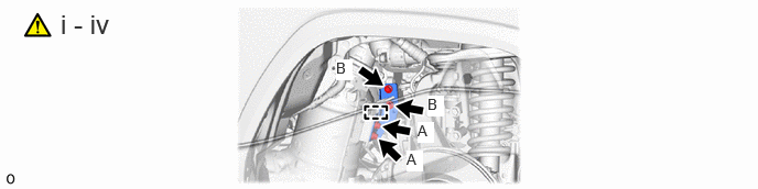
Attach the manifold stay hook to the front exhaust pipe sub-assembly.
Temporarily install the manifold stay with the 2 bolts of A.
Install the 2 bolts of B.
- Torque:
- 43 N*m (438 kgf*cm, 32 ft.*lbf)
Tighten the 2 bolts of A.
- Torque:
- 43 N*m (438 kgf*cm, 32 ft.*lbf)
17435 8.INSTALL EXHAUST PIPE HEAT INSULATOR
- Torque:
- 10 N*m (102 kgf*cm, 7 ft.*lbf)
89425B 9.CONNECT NO. 3 EXHAUST GAS TEMPERATURE SENSOR CONNECTOR (w/ DPF)
89467B 10.CONNECT AIR FUEL RATIO SENSOR CONNECTOR (w/o Urea SCR System)
11.CONNECT DIFFERENTIAL PRESSURE SENSOR
53783 12.INSTALL FRONT FENDER APRON TRIM PACKING B
13.INSTALL FRONT WHEELS
51420 14.INSTALL NO. 2 ENGINE UNDER COVER ASSEMBLY
51410 15.INSTALL NO. 1 ENGINE UNDER COVER ASSEMBLY