1VD-FTV ENGINE MECHANICAL ENGINE ON-VEHICLE INSPECTION
PROCEDURE

 1.INSPECT ENGINE IDLE SPEED
- NOTICE:
-
·
Turn all the electrical systems and the A/C OFF.
·When checking the idle speed, shift the transmission to the neutral position.
- HINT:
-
·
For more information about the GTS, refer to its operator's manual.
·If the GTS is not available, use a tachometer's tester probe as a substitute.
When using the GTS:
Warm up and stop the engine.
Connect the GTS to the DLC3.
Turn the ignition switch to ON.
Enter the following menus:
Powertrain / Engine and ECT / Data List / Engine Speed.
- Powertrain > Engine and ECT > Data List
-
Tester Display Engine Speed - 50003 61 315
Inspect the engine idle speed.
- Standard idle speed:
-
500 to 600 rpm
Turn the ignition switch off.
Disconnect the GTS from the DLC3.
When not using the GTS:
Warm up and stop the engine.
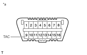
| *a | Front view of DLC3 |
Connect a tester probe of a tachometer to terminal 9 (TAC) of the DLC3 with SST.
- SST
-
09843-18040
Inspect the engine idle speed.
- Standard idle speed:
-
500 to 600 rpm
Disconnect the tester probe from terminal 9 (TAC) of the DLC3.
2.INSPECT MAXIMUM ENGINE SPEED
Start the engine.
Fully depress the accelerator pedal.
Check the maximum engine speed.
- Maximum engine speed:
-
4700 to 4900 rpm
3.INSPECT COMPRESSION
Warm up and stop the engine.
Disconnect the cable from the negative (-) battery terminal.
Remove the No. 1 glow plug connector.
Remove the intercooler assembly.
Click hereEngine / Hybrid System>1VD-FTV (INTAKE / EXHAUST)>INTERCOOLER>REMOVAL
Remove the injection pipe sub-assemblies.
Click hereEngine / Hybrid System>1VD-FTV (INTAKE / EXHAUST)>INTAKE MANIFOLD (w/o DPF)>REMOVAL
Remove the No. 1 glow plug connector.
Reinstall the injection pipe sub-assemblies.
Click hereEngine / Hybrid System>1VD-FTV (INTAKE / EXHAUST)>INTAKE MANIFOLD (w/o DPF)>INSTALLATION
Remove the 8 glow plug assemblies.
Click hereEngine / Hybrid System>1VD-FTV (STARTING)>GLOW PLUG>REMOVAL
Disconnect all connectors from the 8 injector assemblies.
Connect the cable to the negative (-) battery terminal.
Inspect the cylinder compression pressure.
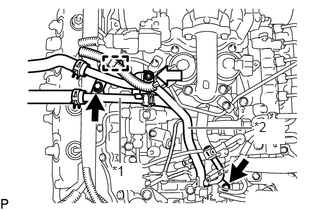
| *1 | No. 2 Water By-pass Pipe |
| *2 | No. 4 Water By-pass Pipe |

|
Bolt |

|
Nut |
RH Side:
Using a clip remover, detach the wire harness clamp.
RH Side:
Remove the 2 bolts and nut. Then disconnect the No. 2 water by-pass pipe and No. 4 water by-pass pipe.
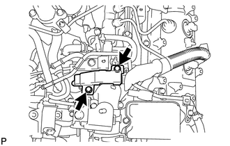
LH Side:
Remove the 2 bolts and disconnect the No. 2 engine room wire.
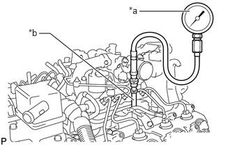
| *a | SST (Compression Gauge) |
| *b | SST (Attachment) |
Insert SST (attachment) into the glow plug assembly hole.
- SST
-
09992-00026 (09992-00410, 09992-00211)
- Torque:
- 13 N*m (133 kgf*cm, 10 ft.*lbf)
Connect SST (compression gauge) to SST (attachment).
While cranking the engine, measure the compression pressure.
- Standard compression pressure (normal condition):
-
2700 kPa (27.5 kgf/cm2, 392 psi) or higher
- Minimum compression pressure:
-
2200 kPa (22.4 kgf/cm2, 319 psi)
- Difference between each cylinder:
-
500 kPa (5.1 kgf/cm2, 73 psi) or less
- NOTICE:
-
·
Use a fully-charged battery so the engine speed can be increased to 280 rpm or more.
·Inspect the other cylinders in the same way.
·Measure the compression as quickly as possible.
If the cylinder compression is low, pour a small amount of engine oil into the cylinder through the glow plug assembly holes. Then inspect the cylinder compression again.
If adding oil increases the compression pressure, the piston rings and/or cylinder bore may be worn or damaged.
If the pressure stays low, the valve may be stuck or seated improperly, or there may be leakage from the gasket.
Remove SST (attachment and compression gauge).
RH Side:
Install the No. 2 water by-pass pipe and No. 4 water by-pass pipe with the 2 bolts and nut.
- Torque:
- 10 N*m (102 kgf*cm, 7 ft.*lbf)
RH Side:
Attach the wire harness clamp.
LH Side:
Install the No. 2 engine room wire with the 2 bolts.
- Torque:
- 13 N*m (133 kgf*cm, 10 ft.*lbf)
Disconnect the cable from the negative (-) battery terminal.
Connect all connectors to the 8 injector assemblies.
Install the 8 glow plug assemblies.
Click hereEngine / Hybrid System>1VD-FTV (STARTING)>GLOW PLUG>INSTALLATION
Install the No. 1 glow plug connector.
Remove the injection pipe sub-assemblies.
Click hereEngine / Hybrid System>1VD-FTV (INTAKE / EXHAUST)>INTAKE MANIFOLD (w/o DPF)>REMOVAL
Reinstall the No. 1 glow plug connector.
Install the injection pipe sub-assemblies.
Click hereEngine / Hybrid System>1VD-FTV (INTAKE / EXHAUST)>INTAKE MANIFOLD (w/o DPF)>INSTALLATION
Install the intercooler assembly.
Click hereEngine / Hybrid System>1VD-FTV (INTAKE / EXHAUST)>INTERCOOLER>INSTALLATION