1VD-FTV INTAKE / EXHAUST INTAKE MANIFOLD(w/o DPF) INSTALLATION
PROCEDURE

 17112 1.INSTALL NO. 2 INTAKE MANIFOLD
Install a new gasket and the No. 2 intake manifold with the 9 bolts.
- Torque:
- 21 N*m (214 kgf*cm, 15 ft.*lbf)
17111 2.INSTALL NO. 1 INTAKE MANIFOLD
Install a new gasket and the No. 1 intake manifold with the 7 bolts.
- Torque:
- 21 N*m (214 kgf*cm, 15 ft.*lbf)
3.INSTALL STARTER HOSE BRACKET SUB-ASSEMBLY
16268 4.INSTALL NO. 1 WATER BY-PASS PIPE
Install a new gasket and the No. 1 water by-pass pipe with the union bolt.
- Torque:
- 58.8 N*m (600 kgf*cm, 43 ft.*lbf)
Install the bolt.
- Torque:
- 10 N*m (102 kgf*cm, 7 ft.*lbf)
23920A 5.INSTALL FUEL COOLER
23763 6.INSTALL NO. 3 NOZZLE LEAKAGE PIPE
23764A 7.INSTALL NO. 4 NOZZLE LEAKAGE PIPE
16283 8.INSTALL NO. 6 WATER BY-PASS HOSE
9.INSTALL EGR VALVE WITH EGR COOLER
25602 10.INSTALL NO. 2 EGR PIPE SUB-ASSEMBLY
25601 11.INSTALL NO. 1 EGR PIPE SUB-ASSEMBLY
16289 12.CONNECT NO. 5 WATER BY-PASS PIPE
17114D 13.INSTALL NO. 3 INTAKE MANIFOLD
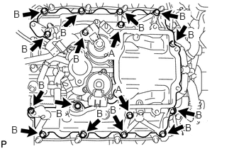
Install a new gasket to the No. 1 intake manifold and a new gasket to the No. 2 intake manifold.
Install the No. 3 intake manifold with the 16 bolts.
- Torque:
- 21 N*m (214 kgf*cm, 15 ft.*lbf)
- Bolt length:
-
Item Length Bolt A 70 mm (2.76 in.) Bolt B 25 mm (0.984 in.)
17113 14.INSTALL INTAKE PIPE
Install a new gasket.
Install the intake pipe with the 4 bolts and 2 nuts.
- Torque:
- 21 N*m (214 kgf*cm, 15 ft.*lbf)
25614 15.INSTALL NO. 4 EGR PIPE
Install 2 new gaskets to the pipe.
Install the No. 4 EGR pipe with the 4 bolts.
- Torque:
- 21 N*m (214 kgf*cm, 15 ft.*lbf)
23801L 16.INSTALL FUEL FILTER TO INJECTION PUMP FUEL PIPE SUB-ASSEMBLY
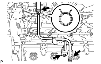
| *a | Marking |
Connect the fuel pump hose and No. 1 fuel hose to the fuel filter to injection pump fuel pipe sub-assembly, and slide the clamp to secure the hoses.
- HINT:
-
·
Align the markings and connect the hose.
·Align the pinching portion of the clamp with the hose marking and connect the hose.
Install the fuel filter to injection pump fuel pipe sub-assembly with the bolt.
- Torque:
- 10 N*m (102 kgf*cm, 7 ft.*lbf)
23810A 17.INSTALL COMMON RAIL LH
23820A 18.INSTALL COMMON RAIL RH
23805B 19.INSTALL NO. 5 FUEL PIPE SUB-ASSEMBLY
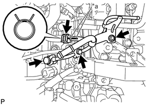
| *a | Marking |
Install a new gasket and the No. 5 fuel pipe sub-assembly with the union bolt.
- Torque:
- 12.3 N*m (125 kgf*cm, 9 ft.*lbf)
Install the nut to the No. 5 fuel pipe sub-assembly.
- Torque:
- 10 N*m (102 kgf*cm, 7 ft.*lbf)
Install the No. 2 injection pipe clamp with the bolt.
- Torque:
- 5.0 N*m (51 kgf*cm, 44 in.*lbf)
Connect the No. 3 fuel hose to the No. 5 fuel pipe sub-assembly, and slide the clamp to secure the hose.
- HINT:
-
·
Align the markings and connect the No. 3 fuel hose.
·Align the pinching portion of the clamp with the No. 3 fuel hose marking and connect the No. 3 fuel hose.
23705 20.INSTALL NO. 5 INJECTION PIPE SUB-ASSEMBLY
23239D 21.INSTALL NO. 1 FUEL HOSE
23706 22.INSTALL NO. 6 INJECTION PIPE SUB-ASSEMBLY
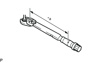
| *a | Fulcrum length |
Using a 17 mm union nut wrench, install a new No. 6 injection pipe to the common rail with the union nuts.
- Torque:
- Specified tightening torque:
-
34 N*m (347 kgf*cm, 25 ft.*lbf)
- NOTICE:
-
Make sure there is no damage or foreign matter on the seal surfaces.
- HINT:
-
·
Calculate the torque wrench reading when changing the fulcrum length of the torque wrench.
Click hereGeneral>INTRODUCTION>REPAIR INSTRUCTION>PRECAUTION
·When using union nut wrench (fulcrum length of 30 mm (1.1811 in.)) + torque wrench (fulcrum length of 180 mm (7.0866 in.)): 29.1 N*m (297 kgf*cm, 21 ft.*lbf)
Install the 2 No. 2 injection pipe clamps with the 2 nuts.
- Torque:
- 5.0 N*m (51 kgf*cm, 44 in.*lbf)
23.INSTALL INJECTION PIPE LH
| *a | Fulcrum length |
Using 17 mm union nut wrench, install 4 new injection pipes to the common rail and fuel injectors with the union nuts.
- Torque:
- Specified tightening torque:
-
34 N*m (347 kgf*cm, 25 ft.*lbf)
- NOTICE:
-
Make sure there is no damage or foreign matter on the seal surfaces.
- HINT:
-
·
Calculate the torque wrench reading when changing the fulcrum length of the torque wrench.
Click hereGeneral>INTRODUCTION>REPAIR INSTRUCTION>PRECAUTION
·When using union nut wrench (fulcrum length of 30 mm (1.1811 in.)) + torque wrench (fulcrum length of 180 mm (7.0866 in.)): 29.1 N*m (297 kgf*cm, 21 ft.*lbf)
24.INSTALL INJECTION PIPE RH
| *a | Fulcrum length |
Using a 17 mm union nut wrench, install 4 new injection pipes to the common rail and fuel injectors with the union nuts.
- Torque:
- Specified tightening torque:
-
34 N*m (347 kgf*cm, 25 ft.*lbf)
- NOTICE:
-
Make sure there is no damage or foreign matter on the seal surfaces.
- HINT:
-
·
Calculate the torque wrench reading when changing the fulcrum length of the torque wrench.
Click hereGeneral>INTRODUCTION>REPAIR INSTRUCTION>PRECAUTION
·When using union nut wrench (fulcrum length of 30 mm (1.1811 in.)) + torque wrench (fulcrum length of 180 mm (7.0866 in.)): 29.1 N*m (297 kgf*cm, 21 ft.*lbf)
17947B 25.INSTALL NO. 3 INTERCOOLER SUPPORT BRACKET
Install the No. 3 intercooler support bracket with the 2 bolts.
- Torque:
- 21 N*m (214 kgf*cm, 15 ft.*lbf)
23265 26.INSTALL NO. 1 GAS FILTER
Install the No. 1 gas filter.
Connect the hose to the intake pipe.
82121 27.CONNECT ENGINE WIRE
RH Side:
Connect the engine wire with the 4 bolts.
- Torque:
- 10 N*m (102 kgf*cm, 7 ft.*lbf)
Attach the 2 clamps.
Connect the 4 fuel injector connectors.
Connect the 2 connectors.
LH Side:
Connect the engine wire with the 7 bolts.
- Torque:
- 10 N*m (102 kgf*cm, 7 ft.*lbf)
Connect the 4 fuel injector connectors.
Connect the 2 connectors.
Rear Side:
Connect the 2 wire harness brackets with the 2 bolts.
- Torque:
- 10 N*m (102 kgf*cm, 7 ft.*lbf)
Connect the 2 ground wires with the 2 bolts.
- Torque:
- 10 N*m (102 kgf*cm, 7 ft.*lbf)
Attach the clamp to the No. 3 intercooler support bracket.
23243C 28.INSTALL FUEL PUMP MOTOR WIRE
Connect the fuel pump motor connector.
Install the bracket with the bolt.
- Torque:
- 10 N*m (102 kgf*cm, 7 ft.*lbf)
16278 29.INSTALL NO. 2 WATER BY-PASS PIPE
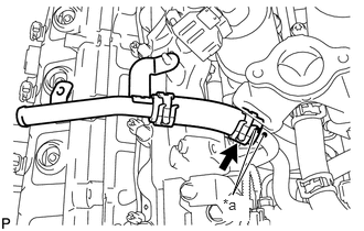
| *a | Marking |
Connect the No. 2 water by-pass pipe, and slide the clamp to secure the hose.
- HINT:
-
·
Align the markings and connect the hose.
·Align the pinching portion of the clamp with the hose marking and connect the hose.
16288 30.INSTALL NO. 4 WATER BY-PASS PIPE
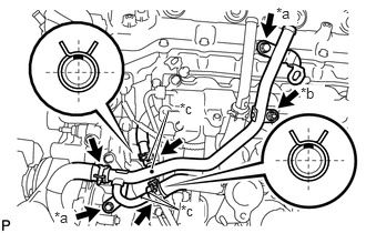
| *a | Bolt |
| *b | Nut |
| *c | Marking |
Connect the inlet water hose, No. 4 water by-pass hose and No. 7 water by-pass hoses to the No. 4 water by-pass pipe, and slide the clamp to secure the hoses.
- HINT:
-
·
Align the markings and connect the hose.
·Align the pinching portion of the clamp with the hose marking and connect the hose.
Install the No. 4 water by-pass pipe with the 2 bolts and nut.
- Torque:
- 10 N*m (102 kgf*cm, 7 ft.*lbf)
- HINT:
-
Tighten the 2 bolts first.
25850 31.INSTALL ELECTRIC VACUUM REGULATING VALVE ASSEMBLY
44761 32.INSTALL VACUUM PUMP TO CONNECTOR TUBE
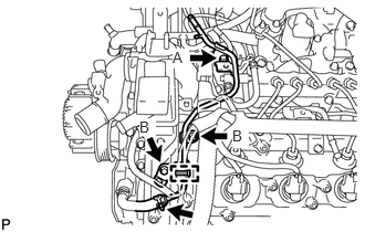
Install the vacuum pump to connector tube with the 3 bolts.
- Torque:
- for bolt A : 21 N*m (214 kgf*cm, 15 ft.*lbf)
- for bolt B : 10 N*m (102 kgf*cm, 7 ft.*lbf)
Connect the union to connector tube hose to the vacuum pump to connector tube, and slide the clamp to secure the hose.
Connect the engine wire clamp to the vacuum pump to connector tube.
82122 33.CONNECT NO. 2 ENGINE WIRE
Connect the No. 2 engine wire with the 2 bolts.
- Torque:
- 13 N*m (133 kgf*cm, 10 ft.*lbf)
44769 34.INSTALL VACUUM RESERVOIR CONNECT TUBE
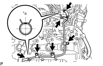
| *a | Upper |
Install the vacuum reservoir connect tube with the 4 bolts.
- Torque:
- for bolt A : 21 N*m (214 kgf*cm, 15 ft.*lbf)
- for bolt B : 10 N*m (102 kgf*cm, 7 ft.*lbf)
Connect the 2 vacuum hoses, and slide the clamp to secure the hose.
- HINT:
-
·
Align the hose markings as shown in the illustration.
·Align the pinching portion of the clamp with the hose marking and connect the hose.
23804D 35.INSTALL NO. 4 FUEL PIPE SUB-ASSEMBLY
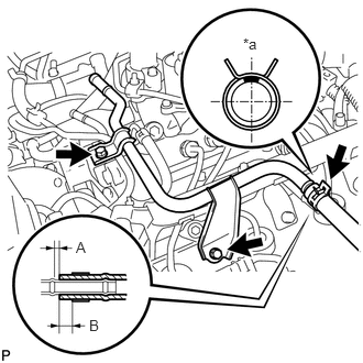
| *a | Upper |
Install the No. 4 fuel pipe sub-assembly with the 2 bolts.
- Torque:
- 10 N*m (102 kgf*cm, 7 ft.*lbf)
Connect the No. 2 fuel hose to the No. 4 fuel pipe sub-assembly, and slide the clamp to secure the hose.
- Standard Distance:
-
Distance Specified Condition A 2.0 to 7.0 mm (0.0787 to 0.276 in.) B 0 to 3.0 mm (0 to 0.118 in.)
- HINT:
-
·
Install the hose so that its direction and position are as shown in the illustration.
·Install the clamp so that its direction and position are as shown in the illustration.
23284A 36.INSTALL NO. 5 FUEL HOSE
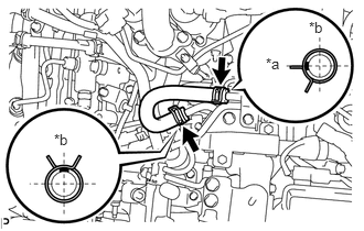
| *a | Front |
| *b | Upper |
Install the No. 5 fuel hose to the No. 5 fuel pipe and No. 4 fuel pipe, and slide the 2 clamps to secure the hose.
- HINT:
-
·
Align the hose markings as shown in the illustration.
·Align the pinching portion of the clamp with the hose marking as shown in the illustration and connect the hose.
16267 37.CONNECT NO. 2 AND NO. 3 WATER BY-PASS HOSES
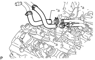
| *a | Marking |
Connect the No. 2 water by-pass hose and No. 3 water by-pass hose, and slide the 2 clamps to secure the hoses.
- HINT:
-
·
Align the markings and connect the hose.
·Align the pinching portion of the clamp with the hose marking and connect the hose.
12142 38.INSTALL NO. 2 ENGINE OIL LEVEL DIPSTICK GUIDE
Apply a light coat of engine oil to a new O-ring.
Install the O-ring to the No. 2 engine oil level dipstick guide.
Install the No. 2 engine oil level dipstick guide with the bolt.
- Torque:
- 10 N*m (102 kgf*cm, 7 ft.*lbf)
15301 39.INSTALL ENGINE OIL LEVEL DIPSTICK
26100G 40.INSTALL DIESEL THROTTLE BODY ASSEMBLY (for Bank 2)
26100G 41.INSTALL DIESEL THROTTLE BODY ASSEMBLY (for Bank 1)
17972 42.INSTALL NO. 2 COOL AIR INLET
17971 43.INSTALL NO. 1 COOL AIR INLET
17940D 44.INSTALL INTERCOOLER ASSEMBLY
45.BLEED AIR FROM FUEL SYSTEM
46.ADD ENGINE COOLANT
47.CONNECT CABLE TO NEGATIVE BATTERY TERMINAL
48.INSPECT FOR FUEL LEAK
49.INSPECT FOR OIL LEAK
50.INSPECT FOR COOLANT LEAK
51442 51.INSTALL NO. 2 ENGINE UNDER COVER