1HZ ENGINE MECHANICAL ENGINE ASSEMBLY REMOVAL
PROCEDURE

 1. PRECAUTION
- NOTICE:
-
After turning the ignition switch off, watching time may be required before disconnecting the cable from the battery terminal. Therefore, make sure to read the disconnecting the cable from the battery terminal notice before proceeding with work.
-
Click hereGeneral>INTRODUCTION>REPAIR INSTRUCTION>PRECAUTION
2.DISCONNECT CABLE FROM NEGATIVE BATTERY TERMINAL
3.DRAIN ENGINE OIL
4.DRAIN ENGINE COOLANT
5.DRAIN MANUAL TRANSMISSION OIL
53301 6.REMOVE HOOD SUB-ASSEMBLY
Disconnect the washer hose.
Remove the 4 bolts and hood sub-assembly.
51442 7.REMOVE NO. 2 ENGINE UNDER COVER
17705 8.REMOVE AIR CLEANER CAP AND HOSE SUB-ASSEMBLY
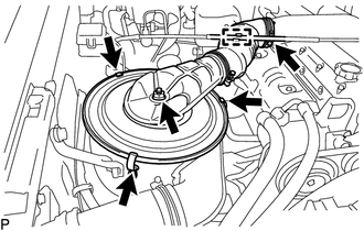
Disconnect the throttle control cable assembly from the air cleaner cap and hose sub-assembly.
Disconnect the 3 clamps from the air cleaner case.
Loosen the hose clamp bolt from the intake pipe.
Remove the nut and air cleaner cap and hose sub-assembly from the air cleaner case and intake pipe.
17801 9.REMOVE AIR CLEANER FILTER ELEMENT SUB-ASSEMBLY
10.REMOVE AIR CLEANER CASE
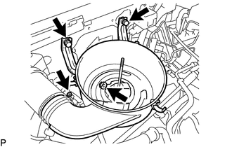
w/ Precleaner:
Loosen the hose clamp bolt from the precleaner.
Remove the 2 bolts, nut and air cleaner case from the body.
78410 11.DISCONNECT THROTTLE CONTROL CABLE ASSEMBLY
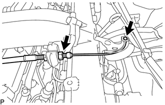
Loosen the nut and disconnect the throttle control cable assembly from the accelerator link assembly and accelerator control cable bracket sub-assembly.
53111 12.REMOVE RADIATOR GRILLE
16470 13.REMOVE RADIATOR RESERVOIR ASSEMBLY
88310A 14.REMOVE NO. 1 V BELT (w/ Air Conditioning System)
16361A 15.REMOVE FAN AND GENERATOR V BELT
16571C 16.REMOVE NO. 1 RADIATOR HOSE
16572D 17.REMOVE NO. 2 RADIATOR HOSE
16701 18.REMOVE FAN SHROUD SUB-ASSEMBLY
16400 19.REMOVE RADIATOR ASSEMBLY
88320 20.DISCONNECT COOLER COMPRESSOR ASSEMBLY (w/ Air Conditioning System)
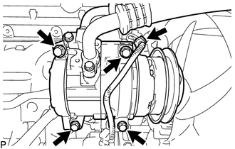
Disconnect the connector from the cooler compressor assembly.
Remove the 4 bolts and disconnect the cooler compressor assembly from the No. 1 compressor mounting bracket.
- HINT:
-
It is not necessary to completely remove the cooler compressor assembly. With the hoses connected to the cooler compressor assembly, hang the cooler compressor assembly on the vehicle body with a rope.
27020 21.REMOVE GENERATOR ASSEMBLY
44360 22.DISCONNECT VANE PUMP OIL RESERVOIR ASSEMBLY
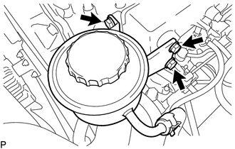
Remove the 3 bolts and disconnect the vane pump oil reservoir assembly from the intake manifold.
44310 23.DISCONNECT VANE PUMP ASSEMBLY
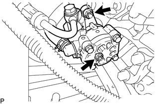
Remove the 2 nuts and disconnect the vane pump assembly from the timing gear case.
24.DISCONNECT CONNECTOR AND HOSE
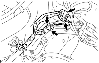
Disconnect the clamp and 4 connectors.
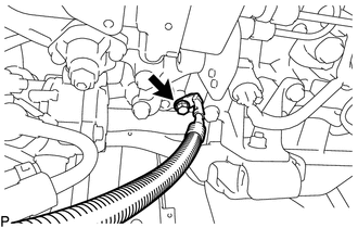
Remove the bolt and disconnect the battery to ground cable from the cylinder block.
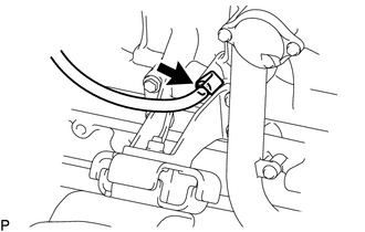
for LHD 2 Battery:
Remove the bolt and disconnect the ground cable from the cylinder block.
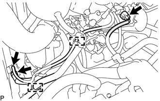
Disconnect the connector from the vacuum switching valve.
Disconnect the 2 clamps from the vacuum hose and power steering tube.
Disconnect the vacuum hose from the vacuum pump assembly.
Slide the clamp and disconnect the union to connector tube hose from the vacuum pump assembly.
25.DISCONNECT FUEL HOSE
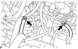
Slide the 2 clamps and disconnect the 2 fuel hoses from the injection pump.
28100 26.REMOVE STARTER ASSEMBLY
17410 27.REMOVE FRONT EXHAUST PIPE ASSEMBLY
28.REMOVE INLET HEATER WATER HOSE
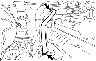
w/o Rear Heater:
Slide the 2 clamps and remove the inlet heater water hose from the heater unit and heater pipe.
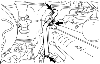
w/ Rear Heater:
Slide the clamp and disconnect the rear outlet heater water hose from the No. 2 heater water hose connector.
Slide the 2 clamps and remove the inlet heater water hose from the heater unit and heater pipe.
29.REMOVE OUTLET HEATER WATER HOSE
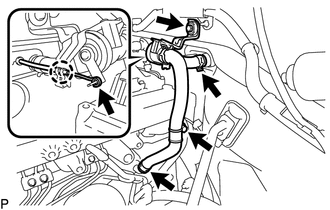
w/o Rear Heater:
Detach the claw and disconnect the water valve cable from the water valve assembly.
Slide the 2 clamps and disconnect the outlet heater water hose from the heater unit and heater pipe.
Remove the 2 bolts and outlet heater water hose from the intake manifold and body.
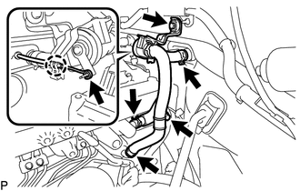
w/ Rear Heater:
Slide the clamp and disconnect the rear inlet heater water hose from the cylinder head sub-assembly.
Detach the claw and disconnect the water valve cable from the water valve assembly.
Slide the 2 clamps and disconnect the outlet heater water hose from the heater unit and heater pipe.
Remove the 2 bolts and outlet heater water hose from the intake manifold and body.
44775E 30.REMOVE WAY TO CONNECTOR HOSE
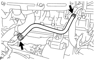
Slide the 2 clamps and remove the way to connector hose from the No. 2 vacuum hose connector and vacuum reservoir connector tube.
37140 31.REMOVE FRONT PROPELLER SHAFT ASSEMBLY
37110 32.REMOVE PROPELLER SHAFT ASSEMBLY
33.REMOVE MANUAL TRANSMISSION WITH TRANSFER
31210 34.REMOVE CLUTCH COVER ASSEMBLY
31250 35.REMOVE CLUTCH DISC ASSEMBLY
13405 36.REMOVE FLYWHEEL SUB-ASSEMBLY
11355 37.REMOVE REAR END PLATE
38.REMOVE ENGINE ASSEMBLY
Attach an engine sling device and hang the engine with a chain block.
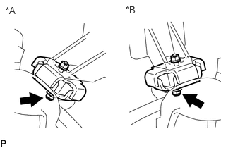
| *A | for RH Side |
| *B | for LH Side |
Remove the 2 nuts and 2 front engine support spacers from the front engine mounting insulator RH and front engine mounting insulator LH.
Lift the engine out of the vehicle carefully.
- NOTICE:
-
Make sure the engine is clear of all wiring and hoses.
Place the engine onto a work bench.
39.INSTALL ENGINE STAND
Install the engine onto an engine stand with bolts.
40.REMOVE FRONT ENGINE MOUNTING INSULATOR
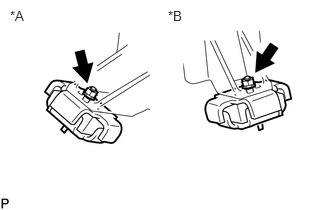
| *A | for RH Side |
| *B | for LH Side |
Remove the 2 nuts and front engine mounting insulator RH and front engine mounting insulator LH from the 2 mounting brackets.