Home › Vehicle Interior › METER / GAUGE / DISPLAY › METER / GAUGE SYSTEM › 2014.08–2016.08
RM25T0E _58 Vehicle Interior _029927 METER / GAUGE / DISPLAY _0137559 METER / GAUGE SYSTEM J

METER / GAUGE / DISPLAY  METER / GAUGE SYSTEM  Tachometer Malfunction  


DESCRIPTION

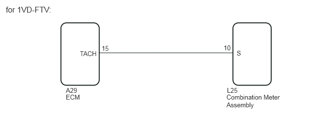
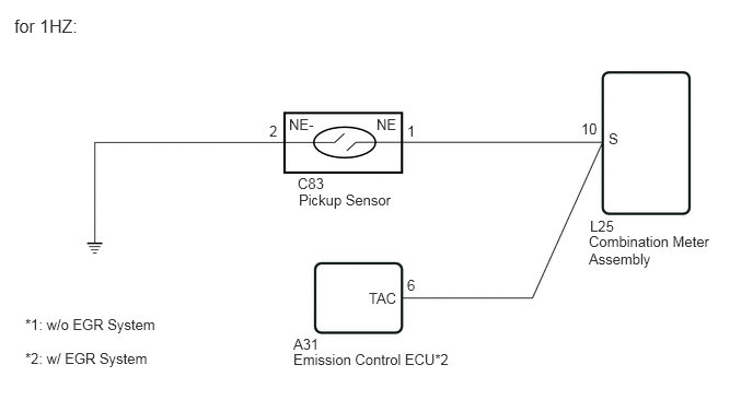
The combination meter receives revolution signals from the ECM*1, emission control ECU*2 or pickup sensor*3. The combination meter displays engine speed data that is calculated based on the data received from the ECM*1, emission control ECU*2 or pickup sensor*3.

*1: for 1GR-FE, 1VD-FTV

*2: for 1HZ (w/ EGR System)

*3: for 1HZ (w/o EGR System)


WIRING DIAGRAM
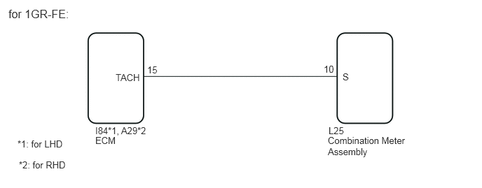
E224935E12
4.885,1.865 6.604,2.073 1.719,0.208 10 false L25 4.875,2.01 6.073,2.333 1.198,0.323 10 false Combination Meter Assembly 5.094,1.063 6.813,1.271 1.719,0.208 10 false S 4.813,0.948 6.531,1.156 1.719,0.208 10 false 10 2.188,0.958 3.906,1.167 1.719,0.208 10 false 15 1.719,1.073 3.438,1.281 1.719,0.208 10 false TACH 1.417,1.865 3.073,2.167 1.656,0.302 10 false I84*1, A29*2 1.417,2.01 3.385,2.323 1.969,0.313 10 false ECM 0.125,0.104 2.115,0.521 1.99,0.417 12 false for 1GR-FE: 0.26,2.063 2.229,2.375 1.969,0.313 10 false *1: for LHD 0.281,2.375 2.25,2.688 1.969,0.313 10 false *2: for RHD

E224935E13
4.885,1.865 6.604,2.073 1.719,0.208 10 false L25 4.875,2.01 6.073,2.333 1.198,0.323 10 false Combination Meter Assembly 5.094,1.063 6.813,1.271 1.719,0.208 10 false S 4.813,0.948 6.531,1.156 1.719,0.208 10 false 10 2.188,0.958 3.906,1.167 1.719,0.208 10 false 15 1.719,1.073 3.438,1.281 1.719,0.208 10 false TACH 1.417,1.865 3.073,2.167 1.656,0.302 10 false A29 1.417,2.01 3.385,2.323 1.969,0.313 10 false ECM 0.125,0.104 2.115,0.521 1.99,0.417 12 false for 1VD-FTV:

E295958E01
2.833,1.667 4.125,2.031 1.292,0.365 10 false C83 2.844,1.823 4.135,2.188 1.292,0.365 10 false Pickup Sensor 2.563,1.167 3.854,1.531 1.292,0.365 10 false 2 3.875,1.167 5.167,1.531 1.292,0.365 10 false 1 2.75,1.104 4.042,1.469 1.292,0.365 10 false NE- 3.583,1.104 4.875,1.469 1.292,0.365 10 false NE 5.531,1.146 6.823,1.51 1.292,0.365 10 false 10 5.792,1.24 7.083,1.604 1.292,0.365 10 false S 5.615,2.073 6.802,2.438 1.188,0.365 10 false L25 5.604,2.219 6.792,2.583 1.188,0.365 10 false Combination Meter Assembly 2.792,3.198 4.292,3.583 1.5,0.385 10 false A31 2.792,3.344 4.365,3.719 1.573,0.375 10 false Emission Control ECU*2 3.51,2.76 5.01,3.146 1.5,0.385 10 false TAC 3.875,2.635 5.375,3.021 1.5,0.385 10 false 6 0.135,0.146 1.427,0.51 1.292,0.365 12 false for 1HZ: 0.24,3.01 1.885,3.24 1.646,0.229 10 false *1: w/o EGR System 0.24,3.333 1.885,3.563 1.646,0.229 10 false *2: w/ EGR System

PROCEDURE

1.CHECK VEHICLE TYPE
a.

Check vehicle type.


Result:
Result Proceed to
for 1GR-FE, 1VD-FTV A
for 1HZ (w/o EGR System) B
for 1HZ (w/ EGR System) C


A

2.CHECK COMBINATION METER ASSEMBLY

B

4.INSPECT PICKUP SENSOR

C

6.CHECK COMBINATION METER ASSEMBLY
2.CHECK COMBINATION METER ASSEMBLY
a.
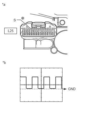
E293691C02
0.177,1.115 0.667,1.354 0.49,0.24 0.667,0.792 0.823,0.792 0.823,0.792 1.302,1.208 true 0.083,0.094 0.396,0.25 0.313,0.156 10 false *a 0.104,2.417 0.417,2.573 0.313,0.156 10 false *b 2.719,3.469 3.063,3.667 0.344,0.198 10 false GND 0.542,0.719 0.885,0.917 0.344,0.198 10 false S 0.313,1.146 0.656,1.344 0.344,0.198 10 false L25
*a Component with harness connected
(Combination Meter Assembly)
*b Waveform


Remove the combination meter assembly with the connector(s) still connected.


b.

Using an oscilloscope, check the signal waveform of the meter.

Measurement Condition
Item Content
Tester Connection L25-10 (S) - Body ground
Tool Setting 5 V/DIV., 10 msec./DIV.
Condition Engine idling

OK:

The waveform displayed is as shown in the illustration.


HINT:

As the engine speed increases, the wavelength shortens.


Result:
Proceed to
OK
NG


OK

REPLACE COMBINATION METER ASSEMBLY

NG

3.CHECK HARNESS AND CONNECTOR (COMBINATION METER ASSEMBLY - ECM)
a.

Disconnect the L25 combination meter assembly connector.


b.

Disconnect the A29*1 or I84*2 ECM connector.

*1: for 1GR-FE (for RHD), 1VD-FTV

*2: for 1GR-FE (for LHD)


c.

Measure the resistance according to the value (s) in the table below.

Standard Resistance:
for 1GR-FE (for RHD), 1VD-FTV
Tester Connection Condition Specified Condition
L25-10 (S) - A29-15 (TACH) Always Below 1 Ω
L25-10 (S) or A29-15 (TACH) - Body ground Always 10 kΩ or higher

for 1GR-FE (for LHD)
Tester Connection Condition Specified Condition
L25-10 (S) - I84-15 (TACH) Always Below 1 Ω
L25-10 (S) or I84-15 (TACH) - Body ground Always 10 kΩ or higher


Result:
Result Proceed to
OK (for 1GR-FE) A
OK (for 1VD-FTV) B
NG C


A

B

C

REPAIR OR REPLACE HARNESS OR CONNECTOR

4.INSPECT PICKUP SENSOR


Result:
Proceed to
OK
NG


OK

5.CHECK HARNESS AND CONNECTOR (PICKUP SENSOR - COMBINATION METER ASSEMBLY AND BODY GROUND)

NG

5.CHECK HARNESS AND CONNECTOR (PICKUP SENSOR - COMBINATION METER ASSEMBLY AND BODY GROUND)
a.

Disconnect the C83 pickup sensor connector.


b.

Disconnect the L25 combination meter assembly connector.


c.

Measure the resistance according to the value (s) in the table below.

Standard Resistance:
Tester Connection Condition Specified Condition
C83-1 (NE) - L25-10 (S) Always Below 1 Ω
C83-2 (NE-) - Body ground Always Below 1 Ω
C83-1 (NE) or L25-10 (S) - Body ground Always 10 kΩ or higher


Result:
Proceed to
OK
NG


OK

REPLACE COMBINATION METER ASSEMBLY

NG

REPAIR OR REPLACE HARNESS OR CONNECTOR

6.CHECK COMBINATION METER ASSEMBLY
a.
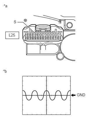
E295959C02
0.198,1.135 0.677,1.385 0.479,0.25 0.625,0.792 0.823,0.792 0.823,0.792 1.313,1.24 true 0.135,0.125 0.448,0.281 0.313,0.156 10 false *a 0.115,2.458 0.427,2.615 0.313,0.156 10 false *b 2.75,3.302 3.188,3.531 0.438,0.229 10 false GND 0.49,0.698 0.927,0.927 0.438,0.229 10 false S 0.313,1.167 0.75,1.396 0.438,0.229 10 false L25
*a Component with harness connected
(Combination Meter Assembly)
*b Waveform


Remove the combination meter assembly with the connector(s) still connected.


b.

Using an oscilloscope, check the signal waveform of the meter.

Measurement Condition
Item Content
Tester Connection L25-10 (S) - Body ground
Tool Setting 0.2 V/DIV., 10 msec./DIV.
Condition Engine idling

OK:

The waveform displayed is as shown in the illustration.


HINT:

As the engine speed increases, the wavelength shortens.


Result:
Proceed to
OK
NG


OK

REPLACE COMBINATION METER ASSEMBLY

NG

7.CHECK HARNESS AND CONNECTOR (COMBINATION METER ASSEMBLY - EMISSION CONTROL ECU)
a.

Disconnect the L25 combination meter assembly connector.


b.

Disconnect the A31 emission control ECU connector.


c.

Measure the resistance according to the value (s) in the table below.

Standard Resistance:
Tester Connection Condition Specified Condition
L25-10 (S) - A31-6 (TAC) Always Below 1 Ω
L25-10 (S) or A31-6 (TAC) - Body ground Always 10 kΩ or higher


Result:
Proceed to
OK
NG


OK

NG

REPAIR OR REPLACE HARNESS OR CONNECTOR