1VD-FTV INTAKE / EXHAUST EXHAUST PIPE(except 5 Door) INSTALLATION
PROCEDURE

 18431 1.INSTALL UPPER CATALYTIC CONVERTER INSULATOR (w/o DPF)
Install the upper catalytic converter insulator with the 2 bolts and nut.
- Torque:
- 21 N*m (214 kgf*cm, 15 ft.*lbf)
18450A 2.INSTALL MONOLITHIC CONVERTER ASSEMBLY (w/o DPF)
Temporarily install a new gasket to the monolithic converter assembly by hand.
- HINT:
-
Be sure to install the gasket as evenly as possible.
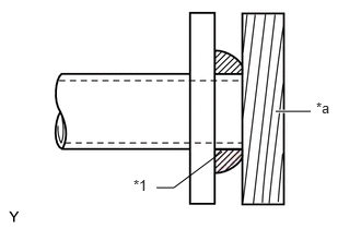
| *1 | Gasket |
| *a | Wooden Block |
Using a plastic-faced hammer and wooden block, tap the gasket onto the monolithic converter assembly so that the gasket is flush with the pipe end.
- NOTICE:
-
·
Install the gasket in the correct direction.
·Do not damage the outer surface of the gasket.
·Do not reuse the gasket.
·Do not push in the gasket with the exhaust pipe when connecting it.
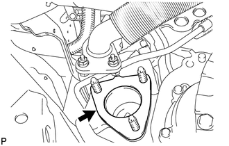
Install a new gasket onto the outlet turbine elbow.
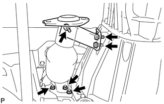
Loosely install the monolithic converter assembly with 3 new nuts.
- HINT:
-
Tighten the nuts until the contact surface of the monolithic converter assembly contacts with the outlet turbine elbow.
Loosely install the center converter protector stay with the 3 bolts.
- HINT:
-
Tighten the bolts so that the position of the monolithic converter assembly can be adjusted in a later step.
Tighten the monolithic converter's nuts.
- Torque:
- 47 N*m (479 kgf*cm, 35 ft.*lbf)
Tighten the center converter protector stay's bolts.
- Torque:
- 43 N*m (438 kgf*cm, 32 ft.*lbf)
17410 3.INSTALL FRONT EXHAUST PIPE ASSEMBLY (w/o DPF)
for Double Cab:
Install the exhaust pipe support cushion to the front exhaust pipe assembly with the 2 nuts.
- Torque:
- 5.5 N*m (56 kgf*cm, 49 in.*lbf)
Inspect the compression spring.
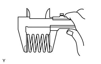
Using a vernier caliper, measure the free length of the compression spring.
- Standard free length:
-
43 mm (1.69 in.)
If the free length is not as specified, replace the compression spring.
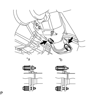
| *a | CORRECT |
| *b | INCORRECT |
Install the front exhaust pipe assembly with the 2 compression springs and 2 bolts.
- Torque:
- 43 N*m (438 kgf*cm, 32 ft.*lbf)
- NOTICE:
-
·
When tightening the bolts, make sure the lengths of the springs are approximately the same.
·Make sure the joint part is movable.
·Make sure the bolts do not get caught on the flange.
for Double Cab:
Install the 2 nuts to the exhaust pipe support cushion.
- Torque:
- 5.5 N*m (56 kgf*cm, 49 in.*lbf)
17410 4.INSTALL FRONT EXHAUST PIPE ASSEMBLY (w/ DPF)
Temporarily install a new gasket to the front exhaust pipe assembly by hand.
- HINT:
-
Be sure to install the gasket as evenly as possible.
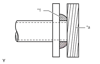
| *1 | Gasket |
| *a | Wooden Block |
Using a plastic-faced hammer and wooden block, tap the gasket onto the front exhaust pipe assembly so that the gasket is flush with the pipe end.
- NOTICE:
-
·
Install the gasket in the correct direction.
·Do not damage the outer surface of the gasket.
·Do not reuse the gasket.
·Do not push in the gasket with the exhaust pipe when connecting it.
Install a new gasket onto the outlet turbine elbow.
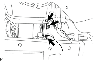
Loosely install the front exhaust pipe assembly with 3 new nuts.
- HINT:
-
Tighten the nuts until the contact surface of the front exhaust pipe assembly contacts with the outlet turbine elbow.
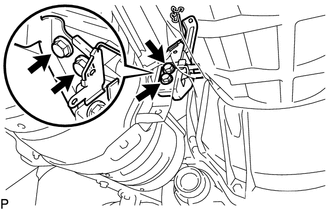
Loosely install the front exhaust pipe assembly to the No. 1 exhaust pipe support with the 4 bolts.
- HINT:
-
Tighten the bolts so that the position of the front exhaust pipe assembly can be adjusted in a later step.
for Single Cab:
Install the No. 2 frame crossmember sub-assembly.
Click hereDrivetrain>H152F (MANUAL TRANSMISSION / TRANSAXLE)>MANUAL TRANSMISSION ASSEMBLY>INSTALLATION
Install the exhaust gas temperature sensor.
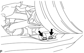
Loosely install the front exhaust pipe assembly to the No. 2 frame crossmember sub-assembly with the 2 bolts.
- HINT:
-
Tighten the bolts so that the position of the front exhaust pipe assembly can be adjusted in a later step.
Tighten the 3 nuts of the front exhaust pipe assembly.
- Torque:
- 47 N*m (479 kgf*cm, 35 ft.*lbf)
Tighten the 4 bolts of the front exhaust pipe assembly to the No. 1 exhaust pipe support.
- Torque:
- 43 N*m (438 kgf*cm, 32 ft.*lbf)
Tighten the 2 bolts of the front exhaust pipe assembly to the No. 2 frame crossmember sub-assembly.
- Torque:
- 19 N*m (194 kgf*cm, 14 ft.*lbf)
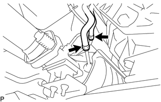
Connect the 2 air hoses to the front exhaust pipe assembly with 2 new clips.
- NOTICE:
-
·
Align the paint marks of the front exhaust pipe assembly and air hose and push on the air hose until it contacts the stopper.
·Make sure that there is no slack in the air hose, and that it is not twisted or bent.
·Take care not to damage the inner or outer surface of the air hose when installing it. If the air hose is damaged, replace it with a new one.
89425B 5.INSTALL NO. 3 EXHAUST GAS TEMPERATURE SENSOR (w/ DPF)
89425A 6.INSTALL NO. 2 EXHAUST GAS TEMPERATURE SENSOR (w/ DPF)
17402 7.INSTALL FRONT NO. 2 EXHAUST PIPE SUB-ASSEMBLY (w/ DPF)
Inspect the compression spring.
Using a vernier caliper, measure the free length of the compression spring.
- Standard free length:
-
43 mm (1.69 in.)
If the free length is not as specified, replace the compression spring.
for Model Code #J78 Series:
Install the exhaust pipe damper to the front No. 2 exhaust pipe assembly with the 2 bolts and 2 nuts.
- Torque:
- 19 N*m (194 kgf*cm, 14 ft.*lbf)
Install the front No. 2 exhaust pipe assembly to the front exhaust pipe assembly with the 2 bolts and 2 compression springs.
- Torque:
- 43 N*m (438 kgf*cm, 32 ft.*lbf)
- NOTICE:
-
·
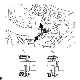 0.958,2.125 1.271,2.281 0.313,0.156 10 false *a 2.177,2.146 2.49,2.302 0.313,0.156 10 false *b
*a CORRECT *b INCORRECT
·When tightening the bolts, make sure the lengths of the springs are approximately the same.
·Make sure the joint part is movable.
·Make sure the bolts do not get caught on the flange.
for Model Code #J79 Series:
Install the exhaust pipe support cushion to the front No. 2 exhaust pipe sub-assembly with the 2 nuts.
- Torque:
- 5.5 N*m (56 kgf*cm, 49 in.*lbf)
Temporarily install the front No. 2 exhaust pipe sub-assembly with the 2 bolts and 2 compression springs labeled A, and the 2 nuts labeled B.
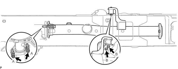
Tighten the bolts labeled A.
- Torque:
- 43 N*m (438 kgf*cm, 32 ft.*lbf)
- NOTICE:
-
·
0.958,2.125 1.271,2.281 0.313,0.156 10 false *a 2.177,2.146 2.49,2.302 0.313,0.156 10 false *b
*a CORRECT *b INCORRECT
·When tightening the bolts, make sure the lengths of the springs are approximately the same.
·Make sure the joint part is movable.
·Make sure the bolts do not get caught on the flange.
Tighten the nuts labeled B.
- Torque:
- 5.5 N*m (56 kgf*cm, 49 in.*lbf)
89467B 8.INSTALL AIR FUEL RATIO SENSOR (w/ DPF)
51203 9.INSTALL NO. 2 FRAME CROSSMEMBER SUB-ASSEMBLY
17420 10.INSTALL CENTER EXHAUST PIPE ASSEMBLY (for Model Code #J78 Series)
Install the exhaust pipe support cushion to the support bracket with the 2 nuts. Then install the muffler clamp bracket to the exhaust pipe support cushion with the 2 nuts.
- Torque:
- 5.5 N*m (56 kgf*cm, 49 in.*lbf)
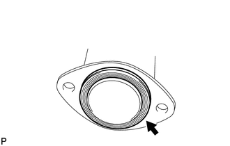
Install a new gasket onto the front exhaust pipe assembly.
Install the exhaust pipe support cushion to the center exhaust pipe assembly with the 2 nuts.
- Torque:
- 5.5 N*m (56 kgf*cm, 49 in.*lbf)
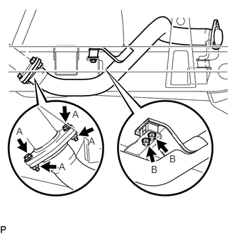
Temporarily install the center exhaust pipe assembly with 2 new bolts and 2 new nuts labeled A, and the 2 nuts labeled B.
Tighten the bolts and nuts labeled A.
- Torque:
- 48 N*m (489 kgf*cm, 35 ft.*lbf)
Tighten the nuts labeled B.
- Torque:
- 5.5 N*m (56 kgf*cm, 49 in.*lbf)
17420 11.INSTALL CENTER EXHAUST PIPE ASSEMBLY (for Model Code #J79 Series)
Install the exhaust pipe support cushion to the support bracket with the 2 nuts. Then install the muffler clamp bracket to the exhaust pipe support cushion with the 2 nuts.
- Torque:
- 5.5 N*m (56 kgf*cm, 49 in.*lbf)
Install a new gasket onto the front exhaust pipe assembly.
except Double Cab w/o DPF:
Install the exhaust pipe support cushion to the center exhaust pipe assembly with the 2 nuts.
- Torque:
- 5.5 N*m (56 kgf*cm, 49 in.*lbf)
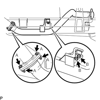
Temporarily install the center exhaust pipe assembly with 2 new bolts and 2 new nuts labeled A, and the 2 nuts labeled B.
Tighten the bolts and nuts labeled A.
- Torque:
- 48 N*m (489 kgf*cm, 35 ft.*lbf)
Tighten the nuts labeled B.
- Torque:
- 5.5 N*m (56 kgf*cm, 49 in.*lbf)
for Double Cab w/ DPF:
Install the center exhaust pipe assembly with 2 new nuts.
- Torque:
- 48 N*m (489 kgf*cm, 35 ft.*lbf)
for Double Cab:
Install the center exhaust pipe assembly with 2 new nuts.
- Torque:
- 48 N*m (489 kgf*cm, 35 ft.*lbf)
51447C 12.INSTALL TRANSFER CASE PROTECTOR
17430 13.INSTALL TAILPIPE ASSEMBLY
Install the 2 exhaust pipe support cushions to the tailpipe assembly with the 4 nuts.
- Torque:
- 5.5 N*m (56 kgf*cm, 49 in.*lbf)
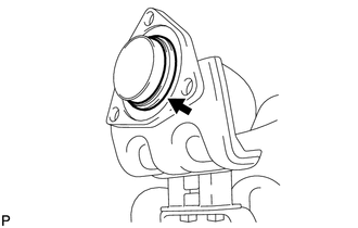
Install a new gasket onto the center exhaust pipe assembly.
Temporarily install the tailpipe assembly with 3 new bolts and 3 new nuts labeled A, and the 4 nuts labeled B.
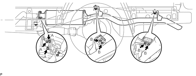
Tighten the nuts labeled B.
- Torque:
- 5.5 N*m (56 kgf*cm, 49 in.*lbf)
Tighten the bolts and nuts labeled A.
- Torque:
- 48 N*m (489 kgf*cm, 35 ft.*lbf)
14.INSPECT FOR EXHAUST GAS LEAK