H150F MANUAL TRANSMISSION / TRANSAXLE MANUAL TRANSMISSION ASSEMBLY(for 1VD-FTV) INSTALLATION
PROCEDURE

 31236B 1.INSTALL RELEASE FORK SUPPORT
31237 2.INSTALL CLUTCH RELEASE FORK SUPPORT BOOT
31204 3.INSTALL CLUTCH RELEASE FORK SUB-ASSEMBLY
4.INSTALL WIRE HARNESS CLAMP BRACKET
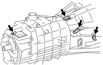
Install the 4 wire harness clamp brackets with the 4 bolts.
- Torque:
- 30 N*m (306 kgf*cm, 22 ft.*lbf)
5.INSTALL TRANSFER ASSEMBLY
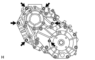
Install the transfer assembly to the manual transmission with the 6 bolts.
- Torque:
- 68.6 N*m (700 kgf*cm, 51 ft.*lbf)
6.INSTALL MANUAL TRANSMISSION WITH TRANSFER
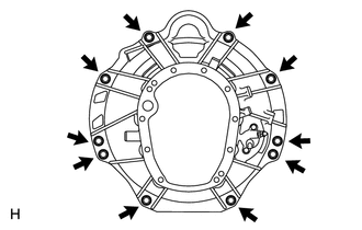
Install the manual transmission with transfer with the 10 bolts.
- Torque:
- 71.6 N*m (730 kgf*cm, 53 ft.*lbf)
7.CONNECT WIRE HARNESS
Connect the connectors and clamps, and then connect the wire harness to the manual transmission with transfer.
Tilt up the manual transmission with transfer.
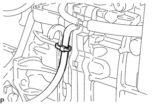
Install the wire harness clamp and connect the wire harness to the manual transmission with transfer.
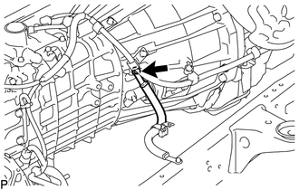
Connect the ground cable with the bolt.
- Torque:
- 13 N*m (133 kgf*cm, 10 ft.*lbf)
12371 8.INSTALL REAR ENGINE MOUNTING INSULATOR
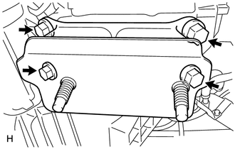
Install the rear engine mounting insulator to the manual transmission with the 4 bolts.
- Torque:
- 59 N*m (602 kgf*cm, 44 ft.*lbf)
51203 9.INSTALL NO. 2 FRAME CROSSMEMBER SUB-ASSEMBLY
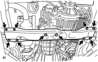
Install the No. 2 frame crossmember sub-assembly with the 2 nuts.
- Torque:
- 74 N*m (755 kgf*cm, 55 ft.*lbf)
Install the 8 bolts.
- Torque:
- 46 N*m (469 kgf*cm, 34 ft.*lbf)
12140 10.INSTALL OIL PAN COVER
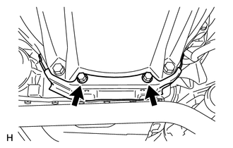
Install the oil pan cover with the 2 bolts.
- Torque:
- 21 N*m (214 kgf*cm, 15 ft.*lbf)
11.INSTALL FRONT STABILIZER BRACKET LH
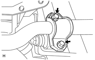
Install the front stabilizer bracket LH with the 2 bolts.
- Torque:
- 29.7 N*m (303 kgf*cm, 22 ft.*lbf)
12.INSTALL FRONT STABILIZER BRACKET RH
- HINT:
-
Use the same procedure described for the LH side.
31470 13.INSTALL CLUTCH RELEASE CYLINDER ASSEMBLY
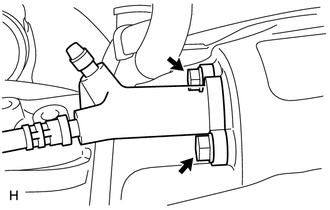
Install the clutch release cylinder assembly with the 2 bolts.
- Torque:
- 11.8 N*m (120 kgf*cm, 9 ft.*lbf)
18450A 14.INSTALL MONOLITHIC CONVERTER ASSEMBLY
37110 15.INSTALL REAR PROPELLER SHAFT ASSEMBLY
37140 16.INSTALL FRONT PROPELLER SHAFT ASSEMBLY
51447C 17.INSTALL TRANSFER CASE PROTECTOR
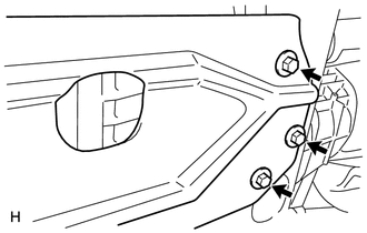
Install the transfer case protector to the crossmember with the 3 bolts.
- Torque:
- 18 N*m (184 kgf*cm, 13 ft.*lbf)
18.ADD MANUAL TRANSMISSION OIL
36308 19.CONNECT HIGH AND LOW SHIFT ROD SUB-ASSEMBLY
Connect the high and low shift rod sub-assembly with the washer and nut.
- Torque:
- 11.76 N*m (120 kgf*cm, 9 ft.*lbf)
20.INSTALL TRANSFER SHIFT LEVER ASSEMBLY
21.INSPECT AND ADJUST TRANSFER SHIFT LEVER ASSEMBLY
33530F 22.INSTALL TRANSMISSION SHIFT LEVER ASSEMBLY
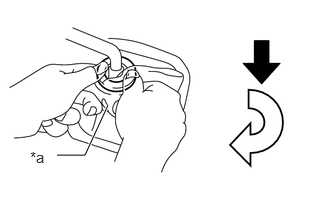
| *a | Cloth or Equivalent |

|
Down |

|
Clockwise |
Cover the transmission shift lever cap with a cloth or equivalent.
While pressing down on the transmission shift lever cap, turn it clockwise to install the transmission shift lever.
58286 23.INSTALL NO. 1 SHIFT AND SELECT LEVER BOOT
36303 24.INSTALL SHIFT LEVER KNOB SUB-ASSEMBLY
89441A 25.INSTALL DECELERATION SENSOR (w/ ABS)
89170 26.INSTALL AIRBAG SENSOR ASSEMBLY WITH AIRBAG SENSOR BRACKET (w/ Airbag System)
89179A 27.INSTALL AIRBAG SENSOR COVER
58811B 28.INSTALL CONSOLE BOX
58191 29.INSTALL FRONT FLOOR FOOTREST
62112A 30.INSTALL COWL SIDE TRIM SUB-ASSEMBLY LH
for 2 door: (Click hereVehicle Interior>INTERIOR PANELS / TRIM>ROOF HEADLINING (for Single Cab)>INSTALLATION)
for 4 door: (Click hereVehicle Interior>INTERIOR PANELS / TRIM>ROOF HEADLINING (for Double Cab)>INSTALLATION)
62111A 31.INSTALL COWL SIDE TRIM SUB-ASSEMBLY RH
- HINT:
-
Use the same procedure described for the LH side.
67914 32.INSTALL FRONT DOOR SCUFF PLATE LH
for 2 door: (Click hereVehicle Interior>INTERIOR PANELS / TRIM>ROOF HEADLINING (for Single Cab)>INSTALLATION)
for 4 door: (Click hereVehicle Interior>INTERIOR PANELS / TRIM>ROOF HEADLINING (for Double Cab)>INSTALLATION)
67913 33.INSTALL FRONT DOOR SCUFF PLATE RH
- HINT:
-
Use the same procedure described for the LH side.
87240 34.INSTALL HEATER WATER VALVE ASSEMBLY
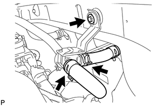
Install the heater water valve assembly to the vehicle with the bolt.
- Torque:
- 5.0 N*m (51 kgf*cm, 44 in.*lbf)
Connect the 2 hoses to the heater water valve assembly and slide the 2 clamps to secure it.
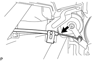
Connect the cable to the heater water valve assembly.
16371 35.INSTALL FAN PULLEY
16711 36.INSTALL FAN SHROUD
16470 37.INSTALL RADIATOR RESERVOIR ASSEMBLY
17875 38.INSTALL INTAKE AIR CONNECTOR PIPE
17805 39.INSTALL INTAKE AIR CONNECTOR SUB-ASSEMBLY
40.INSTALL AIR CLEANER CASE SUB-ASSEMBLY
17705 41.INSTALL AIR CLEANER CAP SUB-ASSEMBLY
17881 42.INSTALL NO. 1 AIR CLEANER HOSE
16571C 43.INSTALL NO. 1 RADIATOR HOSE
44.ADD ENGINE COOLANT
45.CONNECT CABLE TO NEGATIVE BATTERY TERMINAL
46.PERFORM DIAGNOSTIC SYSTEM CHECK
47.CHECK SRS WARNING LIGHT
48.INSPECT FOR ENGINE COOLANT LEAK
49.INSPECT FOR EXHAUST GAS LEAK
51442 50.INSTALL NO. 2 ENGINE UNDER COVER