METER / GAUGE / DISPLAY METER / GAUGE SYSTEM Engine Coolant Temperature Gauge Malfunction
DESCRIPTION
w/ VSC
In this circuit, the combination meter assembly receives engine coolant temperature signals from the ECM via the CAN communication system. The combination meter assembly displays the engine coolant temperature that is calculated based on the data received from the ECM.
w/o VSC
The combination meter receives an engine coolant temperature signal from the ECM*1, engine coolant temperature sensor*2 or water temperature sender gauge assembly*3. The engine coolant temperature gauge needle position changes based on the resistance of the ECM*1, engine coolant temperature sensor*2 or water temperature sender gauge assembly*3.
*1: for 1GR-FE
*2: for 1VD-FTV
*3: for 1HZ
WIRING DIAGRAM
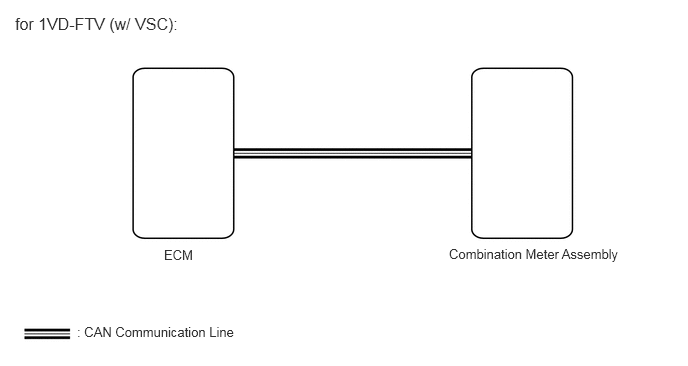
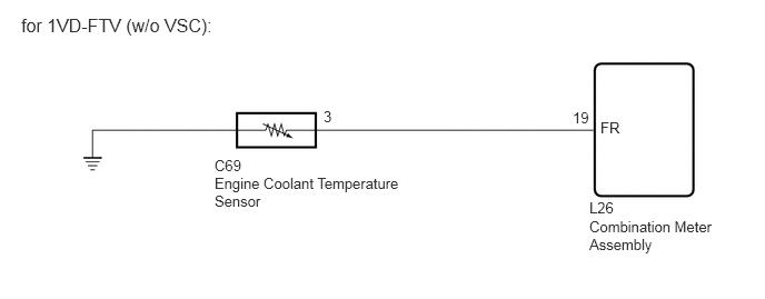
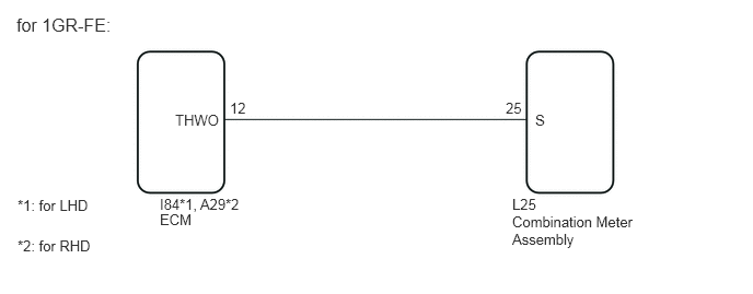
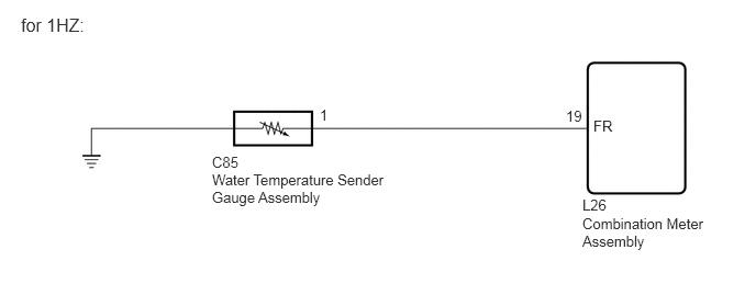
PROCEDURE
Check vehicle type.
- Result:
-
Result Proceed to for 1VD-FTV (w/ VSC) A for 1VD-FTV (w/o VSC) B for 1GR-FE C for 1HZ D
A
B
C
D
Check for DTCs.
Click hereVehicle Interior>METER / GAUGE / DISPLAY>METER / GAUGE SYSTEM>DTC CHECK / CLEAR
- Body Electrical > Combination Meter > Trouble Codes
- 50001 122
- OK:
-
No DTCs are output.
- Result:
-
Proceed to OK NG
OK
NG
Click hereVehicle Interior>METER / GAUGE / DISPLAY>METER / GAUGE SYSTEM>DIAGNOSTIC TROUBLE CODE CHART
Check for DTCs.
Click hereEngine / Hybrid System>1VD-FTV (ENGINE CONTROL)>ECD SYSTEM (w/ DPF)>DTC CHECK / CLEAR
- Powertrain > Engine and ECT > Trouble Codes
- 50001 61
- OK:
-
No DTCs are output.
- Result:
-
Proceed to OK NG
OK
NG
Click hereEngine / Hybrid System>1VD-FTV (ENGINE CONTROL)>ECD SYSTEM (w/ DPF)>DIAGNOSTIC TROUBLE CODE CHART
Using the GTS, perform the Active Test.
Click hereVehicle Interior>METER / GAUGE / DISPLAY>METER / GAUGE SYSTEM>DATA LIST / ACTIVE TEST
- Body Electrical > Combination Meter > Active Test
-
Tester Display Measurement Item Control Range Diagnostic Note Water Temperature Meter Operation Engine coolant temperature receiver gauge OFF, LOW, NORMAL or HIGH -
- Body Electrical > Combination Meter > Active Test
-
Tester Display Water Temperature Meter Operation - 50004 122 89
- OK:
-
Engine coolant temperature receiver gauge indication is normal.
- Result:
-
Proceed to OK NG
OK
NG
Remove the engine coolant temperature sensor.
Click hereEngine / Hybrid System>1VD-FTV (ENGINE CONTROL)>ENGINE COOLANT TEMPERATURE SENSOR>REMOVAL
Inspect the engine coolant temperature sensor.
Click hereEngine / Hybrid System>1VD-FTV (ENGINE CONTROL)>ENGINE COOLANT TEMPERATURE SENSOR>INSPECTION
- Result:
-
Proceed to OK NG
OK
NG
Disconnect the L25 combination meter assembly connector.
Disconnect the C69 engine coolant temperature sensor connector.
Measure the resistance according to the value(s) in the table below.
- Standard Resistance:
-
Tester Connection Condition Specified Condition L25-19 (FR) - C69-3 Always Below 1 Ω L25-19 (FR) or C69-3 - Body ground Always 10 kΩ or higher
- Result:
-
Proceed to OK NG
OK
NG
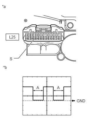
| *a | Component with harness connected (Combination Meter Assembly) |
| *b | Waveform |
Remove the combination meter assembly with the connector(s) still connected.
Click hereVehicle Interior>METER / GAUGE / DISPLAY>COMBINATION METER>REMOVAL
Using an oscilloscope, check the signal waveform of the meter.
| Item | Content |
|---|---|
| Tester Connection | L25-25 (S) - Body ground |
| Tool Setting | 5 V/DIV., 10 msec./DIV. |
| Condition | Engine idling |
- HINT:
-
As the coolant temperature rises, the period "A" shown in the illumination becomes longer.
- OK:
-
The waveform displayed is as shown in the illustration.
- Result:
-
Proceed to OK NG
OK
NG
Disconnect the L25 combination meter assembly connector.
Disconnect the I84*1 or A29*2 ECM connector.
*1: for LHD
*2: for RHD
Measure the resistance according to the value(s) in the table below.
- Standard Resistance:
-
for LHD Tester Connection Condition Specified Condition L25-25 (S) - I84-12 (THWO) Always Below 1 Ω L25-25 (S) or I84-12 (THWO) - Body ground Always 10 kΩ or higher
-
for RHD Tester Connection Condition Specified Condition L25-25 (S) - A29-12 (THWO) Always Below 1 Ω L25-25 (S) or A29-12 (THWO) - Body ground Always 10 kΩ or higher
- Result:
-
Proceed to OK NG
OK
NG
Remove the water temperature sender gauge assembly.
Click hereEngine / Hybrid System>1HZ (ENGINE CONTROL)>ENGINE COOLANT TEMPERATURE SENSOR>REMOVAL
Inspect the water temperature sender gauge assembly.
Click hereEngine / Hybrid System>1HZ (ENGINE CONTROL)>ENGINE COOLANT TEMPERATURE SENSOR>INSPECTION
- Result:
-
Proceed to OK NG
OK
NG
Disconnect the L25 combination meter assembly connector.
Disconnect the C85 water temperature sender gauge assembly connector.
Measure the resistance according to the value(s) in the table below.
- Standard Resistance:
-
Tester Connection Condition Specified Condition L25-19 (FR) - C85-1 Always Below 1 Ω L25-19 (FR) or C85-1 - Body ground Always 10 kΩ or higher
- Result:
-
Proceed to OK NG
OK
NG