Home › Engine / Hybrid System › 1VD-FTV (ENGINE CONTROL) › ECD SYSTEM (w/o EGR System) › 2017.01–2017.09
RM25T0E _51 Engine / Hybrid System _029760 1VD-FTV ENGINE CONTROL _0309414 ECD SYSTEM(w/o EGR System) C

1VD-FTV ENGINE CONTROL  ECD SYSTEM(w/o EGR System)  P062D  Fuel Injector Driver Circuit Performance Bank1  P062E  Fuel Injector Driver Circuit Performance Bank2  


DESCRIPTION

The EDU drives the injectors at high speeds. The EDU delivers high-speed drive signals under high-pressure fuel conditions using the DC/DC converter, which provides a high-voltage and quick-charging system.

Soon after the EDU receives an injection command (#1 to #8) signal from the ECM, the EDU responds to the command with an injector injection confirmation (INJF) signal when the current is applied to the injector.
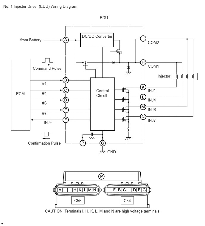
A165473E06
4.229,6.833 4.677,7.104 0.448,0.271 2.5,6.833 2.948,7.104 0.448,0.271 0.115,0.135 2.885,0.365 2.771,0.229 10 false No. 1 Injector Driver (EDU) Wiring Diagram: 0.708,1.302 1.604,1.531 0.896,0.229 10 false from Battery 1.146,2.292 2.24,2.49 1.094,0.198 10 false Command Pulse 0.563,3.177 0.979,3.375 0.417,0.198 10 false ECM 1.479,2.813 1.833,3.01 0.354,0.198 10 false #1 1.531,4.177 1.854,4.365 0.323,0.188 10 false INJF 2.594,6.896 2.875,7.063 0.281,0.167 10 false C55 4.323,6.896 4.594,7.073 0.271,0.177 10 false C54 1.479,3.854 1.833,4.052 0.354,0.198 10 false #7 1.479,3.5 1.833,3.698 0.354,0.198 10 false #6 1.479,3.156 1.844,3.354 0.365,0.198 10 false #4 0.979,4.896 2.198,5.094 1.219,0.198 10 false Confirmation Pulse 3.365,3.073 3.969,3.438 0.604,0.365 10 false Control Circuit 3.75,5.198 4.156,5.396 0.406,0.198 10 false GND 5.167,3.063 5.688,3.26 0.521,0.198 10 false INJ1 5.167,4.104 5.646,4.302 0.479,0.198 10 false INJ7 5.167,3.729 5.646,3.927 0.479,0.198 10 false INJ6 5.167,3.396 5.635,3.594 0.469,0.198 10 false INJ4 1.573,7.26 5.833,7.458 4.26,0.198 10 false CAUTION: Terminals I, H, K, L, M and N are high voltage terminals. 5.167,1.396 5.688,1.594 0.521,0.198 10 false COM2 5.167,2.219 5.688,2.417 0.521,0.198 10 false COM1 2.865,1.177 4.01,1.354 1.146,0.177 10 false DC/DC Converter 3.49,0.531 3.875,0.729 0.385,0.198 10 false EDU 5.51,2.563 6.031,2.76 0.521,0.198 10 false Injector

DTC No. Detection Item DTC Detection Condition Trouble Area MIL Memory
P062D Fuel Injector Driver Circuit Performance Bank1 Open or short in No. 1 injector driver (EDU) or injector circuit
(1 trip detection logic)
·

Open or short in No. 1 injector driver (EDU) circuit

·

Fuel Injector

·

No. 1 EDU

·

ECM


Comes on DTC stored
P062E Fuel Injector Driver Circuit Performance Bank2 Open or short in No. 2 injector driver (EDU) or injector circuit
(1 trip detection logic)
·

Open or short in No. 2 injector driver (EDU) circuit

·

Fuel Injector

·

No. 2 EDU

·

ECM


Comes on DTC stored

HINT:

DTC P062D or P062E is detected when starting the engine and letting it idle for 30 seconds.


MONITOR DESCRIPTION

P062D, P062E (Open or short in EDU or injector circuit):

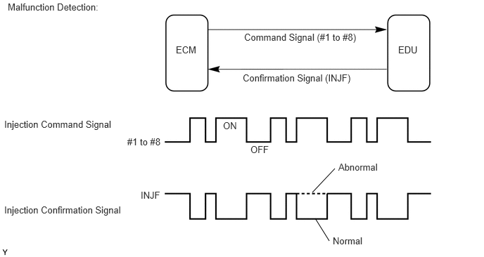
The ECM continuously monitors both injection command (#1 to #8) signals and injection confirmation (INJF) signals. This DTC will be set if the ECM determines that the number of #1 to #8 signals and INJF signals are inconsistent.

The injectors are grounded over a Field Effect Transistor (FET) and a serial resistor. This resistor creates a voltage drop, which is monitored by the EDU (injector drive circuit), in relation to the current drawn by the injector. When the injector current becomes too high, the voltage drop over the resistor exceeds a specified level and no INJF signal for that cylinder is sent to the ECM.

After the engine is started, when there is no injection confirmation (INJF) signal from the No.1 or No. 2 EDU to the ECM even though the ECM sends injection command (#1 to #8) signals to the No. 1 or No. 2 EDU, DTC P062D or DTC P062E is output.

If this DTC is set, the ECM enters fail-safe mode and limits engine power or stops the engine. The fail-safe mode continues until the ignition switch is turned OFF.

A145849E51
4.958,2.5 4.625,2.854 false 4.667,3.24 4.875,3.573 false 0.115,0.021 1.698,0.229 1.583,0.208 10 false Malfunction Detection: 2.604,0.656 3.01,0.854 0.406,0.198 10 false ECM 0.063,1.76 1.75,1.979 1.688,0.219 10 false Injection Command Signal 0.063,3.031 2.021,3.24 1.958,0.208 10 false Injection Confirmation Signal 1.885,2.021 2.438,2.198 0.552,0.177 10 false #1 to #8 2.083,2.813 2.396,3.01 0.313,0.198 10 false INJF 3.302,1.781 3.583,1.979 0.281,0.198 10 false ON 3.615,0.469 5.313,0.688 1.698,0.219 10 false Command Signal (#1 to #8) 3.594,1.073 5.281,1.271 1.688,0.198 10 false Confirmation Signal (INJF) 5.896,0.656 6.281,0.854 0.385,0.198 10 false EDU 3.708,2.135 4.073,2.333 0.365,0.198 10 false OFF 5.01,2.396 5.781,2.594 0.771,0.198 10 false Abnormal 4.927,3.49 5.51,3.688 0.583,0.198 10 false Normal


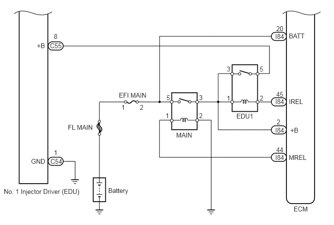
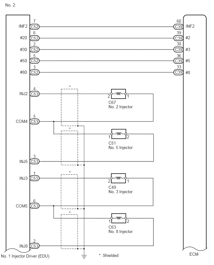
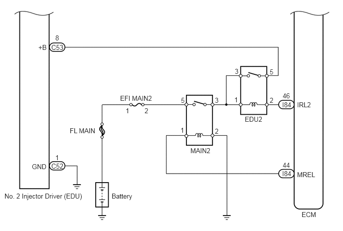
WIRING DIAGRAM
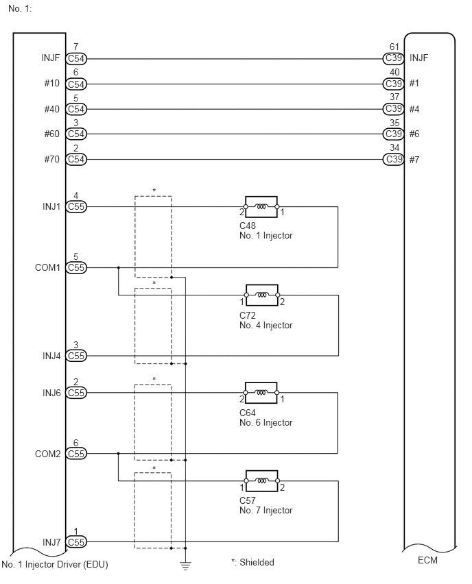
A165780E09
0.125,0.042 0.552,0.229 0.427,0.188 10 false No. 1: 0.625,0.792 0.969,0.958 0.344,0.167 10 false INJF 1.031,0.802 1.375,0.969 0.344,0.167 10 false C54 1.115,0.625 1.229,0.781 0.115,0.156 10 false 7 0.677,1.177 0.969,1.344 0.292,0.167 10 false #10 1.031,1.198 1.365,1.354 0.333,0.156 10 false C54 1.115,1.01 1.229,1.167 0.115,0.156 10 false 6 0.677,1.573 0.969,1.74 0.292,0.167 10 false #40 1.031,1.573 1.375,1.729 0.344,0.156 10 false C54 1.115,1.406 1.229,1.563 0.115,0.156 10 false 5 0.677,1.948 0.969,2.115 0.292,0.167 10 false #60 1.031,1.948 1.375,2.125 0.344,0.177 10 false C54 1.115,1.781 1.229,1.938 0.115,0.156 10 false 3 0.677,2.333 0.969,2.5 0.292,0.167 10 false #70 6.219,0.792 6.563,0.958 0.344,0.167 10 false INJF 6.219,1.177 6.51,1.344 0.292,0.167 10 false #1 6.219,1.573 6.51,1.74 0.292,0.167 10 false #4 6.219,1.948 6.51,2.115 0.292,0.167 10 false #6 6.219,2.344 6.51,2.51 0.292,0.167 10 false #7 1.031,2.333 1.417,2.552 0.385,0.219 10 false C54 5.854,0.792 6.135,0.948 0.281,0.156 10 false C39 5.917,0.625 6.104,0.781 0.188,0.156 10 false 61 5.854,1.188 6.135,1.344 0.281,0.156 10 false C39 5.917,1.01 6.104,1.167 0.188,0.156 10 false 40 5.854,1.563 6.135,1.719 0.281,0.156 10 false C39 5.917,1.385 6.104,1.542 0.188,0.156 10 false 37 5.854,1.948 6.135,2.104 0.281,0.156 10 false C39 5.917,1.781 6.104,1.938 0.188,0.156 10 false 35 5.865,2.333 6.146,2.49 0.281,0.156 10 false C39 5.917,2.156 6.104,2.313 0.188,0.156 10 false 34 1.115,2.167 1.229,2.323 0.115,0.156 10 false 2 0.646,3.052 0.969,3.219 0.323,0.167 10 false INJ1 1.031,3.052 1.354,3.208 0.323,0.156 10 false C55 1.115,2.885 1.229,3.042 0.115,0.156 10 false 4 3.635,3.135 3.75,3.292 0.115,0.156 10 false 2 4.25,3.135 4.365,3.292 0.115,0.156 10 false 1 2.313,2.833 2.427,2.99 0.115,0.156 10 false * 2.313,4.24 2.427,4.396 0.115,0.156 10 false * 2.313,5.698 2.427,5.854 0.115,0.156 10 false * 2.313,7.052 2.427,7.208 0.115,0.156 10 false * 0.646,5.323 0.969,5.49 0.323,0.167 10 false INJ4 1.031,5.323 1.417,5.479 0.385,0.156 10 false C55 1.115,5.156 1.229,5.313 0.115,0.156 10 false 3 0.646,5.885 0.969,6.052 0.323,0.167 10 false INJ6 1.031,5.885 1.406,6.052 0.375,0.167 10 false C55 1.115,5.719 1.229,5.875 0.115,0.156 10 false 2 0.646,8.156 0.969,8.323 0.323,0.167 10 false INJ7 1.031,8.156 1.354,8.323 0.323,0.167 10 false C55 1.115,7.99 1.229,8.146 0.115,0.156 10 false 1 0.531,3.979 0.969,4.146 0.438,0.167 10 false COM1 1.031,3.979 1.406,4.156 0.375,0.177 10 false C55 1.115,3.813 1.229,3.969 0.115,0.156 10 false 5 0.531,6.813 0.969,6.979 0.438,0.167 10 false COM2 1.031,6.813 1.406,6.979 0.375,0.167 10 false C55 1.115,6.646 1.229,6.802 0.115,0.156 10 false 6 3.635,3.344 3.917,3.521 0.281,0.177 10 false C48 3.635,3.49 4.604,3.667 0.969,0.177 10 false No. 1 Injector 3.635,4.5 3.75,4.656 0.115,0.156 10 false 1 4.25,4.5 4.365,4.656 0.115,0.156 10 false 2 3.635,4.708 3.917,4.885 0.281,0.177 10 false C72 3.635,4.854 4.604,5.031 0.969,0.177 10 false No. 4 Injector 3.635,5.979 3.75,6.135 0.115,0.156 10 false 2 4.25,5.979 4.365,6.135 0.115,0.156 10 false 1 3.635,6.188 3.917,6.365 0.281,0.177 10 false C64 3.635,6.333 4.604,6.51 0.969,0.177 10 false No. 6 Injector 3.635,7.323 3.75,7.479 0.115,0.156 10 false 1 4.25,7.323 4.365,7.479 0.115,0.156 10 false 2 3.635,7.521 3.917,7.688 0.281,0.167 10 false C57 3.635,7.667 4.604,7.844 0.969,0.177 10 false No. 7 Injector 3.51,8.458 4.25,8.615 0.74,0.156 10 false *: Shielded 6.344,8.427 6.708,8.615 0.365,0.188 10 false ECM 0.021,8.49 1.719,8.698 1.698,0.208 10 false No. 1 Injector Driver (EDU)

A226746E03
0.667,3.375 1.01,3.552 0.344,0.177 10 false GND 1.083,3.375 1.396,3.563 0.313,0.188 10 false C54 1.156,3.188 1.385,3.365 0.229,0.177 10 false 1 0.792,0.896 1,1.073 0.208,0.177 10 false +B 1.073,0.896 1.375,1.063 0.302,0.167 10 false C55 1.156,0.698 1.385,0.875 0.229,0.177 10 false 8 0.083,4.021 1.792,4.208 1.708,0.188 10 false No. 1 Injector Driver (EDU) 2.323,4 2.813,4.167 0.49,0.167 10 false Battery 1.458,2.646 2.115,2.813 0.656,0.167 10 false FL MAIN 2.552,1.958 3.177,2.104 0.625,0.146 10 false EFI MAIN 3.781,2.813 4.552,2.99 0.771,0.177 10 false MAIN 5.073,2.406 5.521,2.583 0.448,0.177 10 false EDU1 5.906,0.698 6.177,0.854 0.271,0.156 10 false I84 6.198,0.688 6.594,0.844 0.396,0.156 10 false BATT 3.573,2.01 3.698,2.167 0.125,0.156 10 false 5 4.271,2.01 4.396,2.167 0.125,0.156 10 false 3 4.865,1.396 4.99,1.552 0.125,0.156 10 false 3 5.573,1.396 5.698,1.552 0.125,0.156 10 false 5 4.865,2.021 4.99,2.177 0.125,0.156 10 false 1 5.573,2.021 5.698,2.177 0.125,0.156 10 false 2 5.927,0.531 6.135,0.688 0.208,0.156 10 false 20 5.906,2.094 6.177,2.25 0.271,0.156 10 false I84 6.198,2.094 6.573,2.25 0.375,0.156 10 false IREL 5.927,1.938 6.135,2.094 0.208,0.156 10 false 45 5.906,3.292 6.177,3.448 0.271,0.156 10 false I84 6.198,3.292 6.646,3.448 0.448,0.156 10 false MREL 6.302,4.396 6.677,4.552 0.375,0.156 10 false ECM 5.927,3.125 6.135,3.281 0.208,0.156 10 false 44 5.906,2.708 6.177,2.865 0.271,0.156 10 false I84 6.229,2.708 6.49,2.865 0.26,0.156 10 false +B 5.938,2.531 6.094,2.688 0.156,0.156 10 false 2 3.552,2.396 3.677,2.552 0.125,0.156 10 false 1 4.271,2.396 4.396,2.552 0.125,0.156 10 false 2 2.604,2.219 2.729,2.375 0.125,0.156 10 false 1 3,2.219 3.125,2.375 0.125,0.156 10 false 2

A165780E10
0.177,0.083 0.635,0.271 0.458,0.188 10 false No. 2: 0.625,0.792 0.969,0.958 0.344,0.167 10 false INF2 1.031,0.813 1.313,0.979 0.281,0.167 10 false C52 1.115,0.625 1.229,0.781 0.115,0.156 10 false 7 0.677,1.177 0.969,1.344 0.292,0.167 10 false #20 1.031,1.198 1.302,1.354 0.271,0.156 10 false C52 1.115,1.01 1.229,1.167 0.115,0.156 10 false 6 0.677,1.573 0.969,1.74 0.292,0.167 10 false #30 1.031,1.583 1.302,1.74 0.271,0.156 10 false C52 1.115,1.396 1.229,1.552 0.115,0.156 10 false 2 0.677,1.948 0.969,2.115 0.292,0.167 10 false #50 1.031,1.948 1.302,2.104 0.271,0.156 10 false C52 1.115,1.781 1.229,1.938 0.115,0.156 10 false 5 0.677,2.333 0.969,2.5 0.292,0.167 10 false #80 6.219,0.792 6.563,0.958 0.344,0.167 10 false INF2 6.219,1.177 6.51,1.344 0.292,0.167 10 false #2 6.219,1.573 6.51,1.74 0.292,0.167 10 false #3 6.219,1.948 6.51,2.115 0.292,0.167 10 false #5 6.219,2.344 6.51,2.51 0.292,0.167 10 false #8 1.031,2.344 1.302,2.5 0.271,0.156 10 false C52 5.854,0.813 6.135,0.969 0.281,0.156 10 false C39 5.917,0.625 6.104,0.781 0.188,0.156 10 false 60 5.854,1.198 6.135,1.354 0.281,0.156 10 false C39 5.917,1.01 6.104,1.167 0.188,0.156 10 false 39 5.854,1.573 6.135,1.729 0.281,0.156 10 false C39 5.917,1.385 6.104,1.542 0.188,0.156 10 false 38 5.854,1.958 6.135,2.115 0.281,0.156 10 false C39 5.917,1.781 6.104,1.938 0.188,0.156 10 false 36 5.854,2.333 6.135,2.49 0.281,0.156 10 false C39 5.917,2.156 6.104,2.313 0.188,0.156 10 false 33 1.115,2.167 1.229,2.323 0.115,0.156 10 false 3 0.646,3.052 0.969,3.219 0.323,0.167 10 false INJ2 1.031,3.063 1.302,3.208 0.271,0.146 10 false C53 1.115,2.885 1.229,3.042 0.115,0.156 10 false 4 3.604,3.135 3.719,3.292 0.115,0.156 10 false 2 4.25,3.135 4.365,3.292 0.115,0.156 10 false 1 2.313,2.833 2.427,2.99 0.115,0.156 10 false * 2.313,4.24 2.427,4.396 0.115,0.156 10 false * 2.313,5.698 2.427,5.854 0.115,0.156 10 false * 2.313,7.052 2.427,7.208 0.115,0.156 10 false * 0.646,5.323 0.969,5.49 0.323,0.167 10 false INJ5 1.031,5.323 1.333,5.469 0.302,0.146 10 false C53 1.115,5.156 1.229,5.313 0.115,0.156 10 false 3 0.646,5.885 0.969,6.052 0.323,0.167 10 false INJ3 1.021,5.885 1.354,6.063 0.333,0.177 10 false C53 1.115,5.719 1.229,5.875 0.115,0.156 10 false 1 0.646,8.156 0.969,8.323 0.323,0.167 10 false INJ8 1.031,8.156 1.313,8.323 0.281,0.167 10 false C53 1.115,7.99 1.229,8.146 0.115,0.156 10 false 2 0.531,3.979 0.969,4.146 0.438,0.167 10 false COM4 1.031,3.99 1.302,4.146 0.271,0.156 10 false C53 1.115,3.813 1.229,3.969 0.115,0.156 10 false 5 0.531,6.813 0.969,6.979 0.438,0.167 10 false COM5 1.031,6.813 1.365,6.969 0.333,0.156 10 false C53 1.115,6.646 1.229,6.802 0.115,0.156 10 false 6 3.635,3.344 3.917,3.521 0.281,0.177 10 false C67 3.635,3.49 4.604,3.667 0.969,0.177 10 false No. 2 Injector 3.625,4.5 3.74,4.656 0.115,0.156 10 false 1 4.25,4.5 4.365,4.656 0.115,0.156 10 false 2 3.635,4.708 3.948,4.885 0.313,0.177 10 false C51 3.635,4.854 4.604,5.031 0.969,0.177 10 false No. 5 Injector 3.615,5.979 3.729,6.135 0.115,0.156 10 false 2 4.25,5.979 4.365,6.135 0.115,0.156 10 false 1 3.635,6.188 3.927,6.354 0.292,0.167 10 false C49 3.635,6.333 4.604,6.51 0.969,0.177 10 false No. 3 Injector 3.635,7.323 3.75,7.479 0.115,0.156 10 false 1 4.25,7.323 4.365,7.479 0.115,0.156 10 false 2 3.635,7.521 3.917,7.698 0.281,0.177 10 false C63 3.635,7.667 4.604,7.844 0.969,0.177 10 false No. 8 Injector 0.031,8.49 1.75,8.688 1.719,0.198 10 false No. 1 Injector Driver (EDU) 3.313,8.469 4.052,8.625 0.74,0.156 10 false *: Shielded 6.344,8.427 6.708,8.615 0.365,0.188 10 false ECM

A225229E03
0.667,3.396 1.01,3.573 0.344,0.177 10 false GND 1.073,3.385 1.354,3.563 0.281,0.177 10 false C52 1.156,3.208 1.385,3.385 0.229,0.177 10 false 1 0.802,0.906 1.01,1.083 0.208,0.177 10 false +B 1.073,0.906 1.354,1.083 0.281,0.177 10 false C53 1.156,0.708 1.385,0.885 0.229,0.177 10 false 8 0.094,4.01 1.823,4.198 1.729,0.188 10 false No. 2 Injector Driver (EDU) 2.333,4.01 2.823,4.177 0.49,0.167 10 false Battery 1.458,2.646 2.115,2.813 0.656,0.167 10 false FL MAIN 2.51,1.969 3.292,2.115 0.781,0.146 10 false EFI MAIN2 3.979,3.063 4.823,3.24 0.844,0.177 10 false MAIN2 5.115,2.406 5.563,2.583 0.448,0.177 10 false EDU2 3.781,2.01 3.906,2.167 0.125,0.156 10 false 5 4.49,2.01 4.615,2.167 0.125,0.156 10 false 3 4.49,2.656 4.615,2.813 0.125,0.156 10 false 2 4.906,1.406 5.031,1.563 0.125,0.156 10 false 3 5.635,1.417 5.76,1.573 0.125,0.156 10 false 5 4.896,2 5.021,2.156 0.125,0.156 10 false 1 5.635,2.01 5.76,2.167 0.125,0.156 10 false 2 5.896,2.104 6.167,2.26 0.271,0.156 10 false I84 6.208,2.104 6.604,2.26 0.396,0.156 10 false IRL2 5.906,1.917 6.115,2.073 0.208,0.156 10 false 46 5.896,3.542 6.167,3.698 0.271,0.156 10 false I84 6.208,3.563 6.656,3.719 0.448,0.156 10 false MREL 6.302,4.396 6.708,4.552 0.406,0.156 10 false ECM 5.906,3.365 6.115,3.521 0.208,0.156 10 false 44 3.771,2.635 3.896,2.792 0.125,0.156 10 false 1 2.625,2.229 2.75,2.385 0.125,0.156 10 false 1 3.021,2.229 3.146,2.385 0.125,0.156 10 false 2

CAUTION / NOTICE / HINT

NOTICE:


HINT:

Read freeze frame data using the GTS. Freeze frame data records the engine condition when malfunctions are detected. When troubleshooting, freeze frame data can help determine if the vehicle was moving or stationary, if the engine was warmed up or not, and other data from the time the malfunction occurred.


PROCEDURE
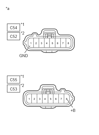
1.CHECK TERMINAL VOLTAGE (EDU POWER SOURCE)
a.
A130531C03
0.25,0.823 0.688,1.083 0.438,0.26 0.25,1.125 0.688,1.385 0.438,0.26 0.25,2.625 0.688,2.885 0.438,0.26 0.25,2.938 0.688,3.198 0.438,0.26 1.042,1.583 0.854,1.833 true 2.333,3.448 2.521,3.719 true 0.344,0.875 0.625,1.052 0.281,0.177 10 false C54 0.719,0.76 0.896,0.906 0.177,0.146 10 false *1 0.344,1.177 0.646,1.354 0.302,0.177 10 false C52 0.719,1.063 0.896,1.208 0.177,0.146 10 false *2 0.344,2.677 0.635,2.854 0.292,0.177 10 false C55 0.708,2.563 0.885,2.708 0.177,0.146 10 false *1 0.344,3 0.635,3.167 0.292,0.167 10 false C53 0.708,2.875 0.885,3.021 0.177,0.146 10 false *2 0.667,1.844 1.042,2.073 0.375,0.229 10 false GND 2.448,3.74 2.823,3.969 0.375,0.229 10 false +B 0.198,0.208 2.583,0.563 2.385,0.354 10 false *a
*1 No. 1
*2 No. 2
*a Front view of wire harness connector
(to EDU)


Disconnect the No. 1 injector driver (EDU) connectors.


b.

Disconnect the No. 2 injector driver (EDU) connectors.


c.

Measure the voltage according to the value(s) in the table below.

Standard voltage:
No. 1
Tester Connection Switch Condition Specified Condition
C55-8 (+B) - C54-1 (GND) Ignition switch ON 11 to 14 V

No. 2
Tester Connection Switch Condition Specified Condition
C53-8 (+B) - C52-1 (GND) Ignition switch ON 11 to 14 V


Result:
Proceed to
OK
NG


OK

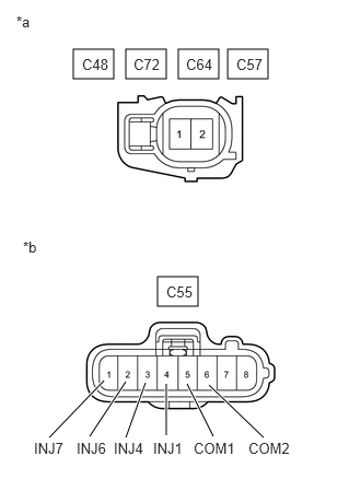
2.CHECK HARNESS AND CONNECTOR (FUEL INJECTOR - EDU)

NG

11.GO TO INJECTOR CIRCUIT
2.CHECK HARNESS AND CONNECTOR (FUEL INJECTOR - EDU)
a.
A311469C04
0.698,0.469 1.083,0.75 0.385,0.281 1.198,0.469 1.583,0.75 0.385,0.281 1.698,0.469 2.083,0.75 0.385,0.281 2.167,0.469 2.552,0.75 0.385,0.281 1.5,2.635 1.885,2.917 0.385,0.281 0.469,4.167 0.99,3.625 true 0.854,4.156 1.198,3.635 true 1.198,4.167 1.385,3.646 true 1.583,4.146 1.583,3.656 true 2.031,4.156 1.781,3.656 true 2.51,4.167 1.99,3.667 true 0.156,0.125 0.469,0.281 0.313,0.156 10 false *a 0.219,2.271 0.531,2.427 0.313,0.156 10 false *b 0.781,0.531 1.094,0.688 0.313,0.156 10 false C48 1.271,0.531 1.583,0.688 0.313,0.156 10 false C72 1.771,0.531 2.083,0.688 0.313,0.156 10 false C64 2.25,0.531 2.563,0.688 0.313,0.156 10 false C57 1.583,2.698 1.896,2.854 0.313,0.156 10 false C55 0.323,4.188 0.698,4.344 0.375,0.156 10 false INJ7 0.729,4.188 1.104,4.344 0.375,0.156 10 false INJ6 1.083,4.188 1.458,4.344 0.375,0.156 10 false INJ4 1.458,4.188 1.833,4.344 0.375,0.156 10 false INJ1 1.844,4.188 2.281,4.344 0.438,0.156 10 false COM1 2.365,4.188 2.813,4.365 0.448,0.177 10 false COM2
*a Front view of wire harness connector
(to Fuel Injector)
*b Front view of wire harness connector
(to No. 1 EDU)


Disconnect the fuel injector connectors.


b.

Disconnect the No. 1 EDU connector.


c.

Measure the resistance according to the value(s) in the table below.

Standard resistance:
No. 1
Tester Connection Condition Specified Condition
C48-2 - C55-4 (INJ1) Always Below 1 Ω
C72-2 - C55-3 (INJ4) Always Below 1 Ω
C64-2 - C55-2 (INJ6) Always Below 1 Ω
C57-2 - C55-1 (INJ7) Always Below 1 Ω
C48-1 - C55-5 (COM1) Always Below 1 Ω
C72-1 - C55-5 (COM1) Always Below 1 Ω
C64-1 - C55-6 (COM2) Always Below 1 Ω
C57-1 - C55-6 (COM2) Always Below 1 Ω
C48-2 or C55-4 (INJ1) - Body ground Always 10 kΩ or higher
C72-2 or C55-3 (INJ4) - Body ground Always 10 kΩ or higher
C64-2 or C55-2 (INJ6) - Body ground Always 10 kΩ or higher
C57-2 or C55-1 (INJ7) - Body ground Always 10 kΩ or higher
C48-1 or C55-5 (COM1) - Body ground Always 10 kΩ or higher
C72-1 or C55-5 (COM1) - Body ground Always 10 kΩ or higher
C64-1 or C55-6 (COM2) - Body ground Always 10 kΩ or higher
C57-1 or C55-6 (COM2) - Body ground Always 10 kΩ or higher
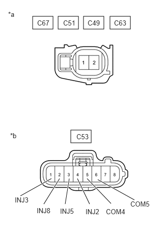


d.
A311469C05
0.667,0.333 1.083,0.594 0.417,0.26 1.188,0.333 1.604,0.594 0.417,0.26 1.708,0.333 2.125,0.594 0.417,0.26 2.25,0.333 2.667,0.594 0.417,0.26 1.448,2.656 1.865,2.917 0.417,0.26 1.833,4.167 1.583,3.646 true 2.75,4.083 2,3.667 true 2.271,4.156 1.781,3.646 true 1.333,4.167 1.417,3.646 true 0.896,4.167 1.219,3.646 true 0.417,4 1.052,3.646 true 0.167,0.208 0.479,0.406 0.313,0.198 10 false *a 0.208,2.688 0.521,2.885 0.313,0.198 10 false *b 1.563,2.708 2.021,2.906 0.458,0.198 10 false C53 0.76,0.385 1.052,0.563 0.292,0.177 10 false C67 1.292,0.385 1.583,0.552 0.292,0.167 10 false C51 1.792,0.385 2.094,0.563 0.302,0.177 10 false C49 2.333,0.385 2.635,0.573 0.302,0.188 10 false C63 0.302,4 0.917,4.198 0.615,0.198 10 false INJ3 0.75,4.219 1.365,4.417 0.615,0.198 10 false INJ8 1.229,4.229 1.844,4.427 0.615,0.198 10 false INJ5 1.75,4.24 2.365,4.438 0.615,0.198 10 false INJ2 2.167,4.24 2.781,4.438 0.615,0.198 10 false COM4 2.667,4.083 3.281,4.281 0.615,0.198 10 false COM5
*a Front view of wire harness connector
(to Fuel Injector)
*b Front view of wire harness connector
(to No. 2 EDU)


Disconnect the C67, C51, C49 and C63 furl injector connectors.


e.

Disconnect the C53 No. 2 EDU connector.


f.

Measure the resistance according to the value(s) in the table below.

Standard resistance:
No. 2
Tester Connection Condition Specified Condition
C67-2 - C53-4 (INJ2) Always Below 1 Ω
C51-2 - C53-3 (INJ5) Always Below 1 Ω
C49-2 - C53-1 (INJ3) Always Below 1 Ω
C63-2 - C53-2 (INJ8) Always Below 1 Ω
C67-1 - C53-5 (COM4) Always Below 1 Ω
C51-1 - C53-5 (COM4) Always Below 1 Ω
C49-1 - C53-6 (COM5) Always Below 1 Ω
C63-1 - C53-6 (COM5) Always Below 1 Ω
C67-2 or C53-4 (INJ2) -Body ground Always 10 kΩ or higher
C51-2 or C53-3 (INJ5) -Body ground Always 10 kΩ or higher
C49-2 or C53-1 (INJ3) -Body ground Always 10 kΩ or higher
C63-2 or C53-2 (INJ8) -Body ground Always 10 kΩ or higher
C67-1 or C53-5 (COM4) -Body ground Always 10 kΩ or higher
C51-1 or C53-5 (COM4) -Body ground Always 10 kΩ or higher
C49-1 or C53-6 (COM5) -Body ground Always 10 kΩ or higher
C63-1 or C53-6 (COM5) -Body ground Always 10 kΩ or higher


Result:
Proceed to
OK
NG


OK

3.CHECK HARNESS AND CONNECTOR (EDU - ECM)

NG

10.REPAIR OR REPLACE HARNESS OR CONNECTOR
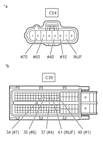
3.CHECK HARNESS AND CONNECTOR (EDU - ECM)
a.
A311470C04
1.521,0.281 1.938,0.563 0.417,0.281 1.417,2.427 1.833,2.708 0.417,0.281 0.844,1.781 1.24,1.271 true 1.219,1.781 1.427,1.271 true 1.677,1.802 1.813,1.281 true 2.094,1.802 2.01,1.281 true 2.552,1.792 2.208,1.281 true 0.396,4.271 1.406,3.208 true 0.969,4.281 1.5,3.208 true 1.552,4.271 1.667,3.208 true 2.052,4.292 1.76,3.292 true 2.76,4.281 1.938,3.208 true 0.125,0.125 0.438,0.281 0.313,0.156 10 false *a 0.177,2.104 0.49,2.26 0.313,0.156 10 false *b 1.635,0.344 1.948,0.5 0.313,0.156 10 false C54 1.51,2.49 1.823,2.646 0.313,0.156 10 false C39 0.688,1.802 1,1.958 0.313,0.156 10 false #70 1.104,1.802 1.417,1.958 0.313,0.156 10 false #60 1.573,1.802 1.885,1.958 0.313,0.156 10 false #40 2,1.802 2.313,1.958 0.313,0.156 10 false #10 2.448,1.802 2.896,1.969 0.448,0.167 10 false INJF 0.208,4.302 0.698,4.458 0.49,0.156 10 false 34 (#7) 0.781,4.302 1.271,4.458 0.49,0.156 10 false 35 (#6) 1.365,4.302 1.854,4.458 0.49,0.156 10 false 37 (#4) 1.938,4.302 2.5,4.458 0.563,0.156 10 false 61 (INJF) 2.594,4.302 3.083,4.458 0.49,0.156 10 false 40 (#1)
*a Front view of wire harness connector
(to No. 1 EDU)
*b Front view of wire harness connector
(to ECM)


Disconnect the No. 1 EDU connector.


b.

Disconnect the ECM connector.


c.

Measure the resistance according to the value(s) in the table below.

Standard resistance:
No. 1
Tester Connection Condition Specified Condition
C54-6 (#10) - C39-40 (#1) Always Below 1 Ω
C54-5 (#40) - C39-37 (#4) Always Below 1 Ω
C54-3 (#60) - C39-35 (#6) Always Below 1 Ω
C54-2 (#70) - C39-34 (#7) Always Below 1 Ω
C54-7 (INJF) - C39-61 (INJF) Always Below 1 Ω
C54-6 (#10) or C39-40 (#1) - Body ground Always 10 kΩ or higher
C54-5 (#40) or C39-37 (#4) - Body ground Always 10 kΩ or higher
C54-3 (#60) or C39-35 (#6) - Body ground Always 10 kΩ or higher
C54-2 (#70) or C39-34 (#7) - Body ground Always 10 kΩ or higher
C54-7 (INJF) or C39-61 (INJF) - Body ground Always 10 kΩ or higher


d.
A311470C05
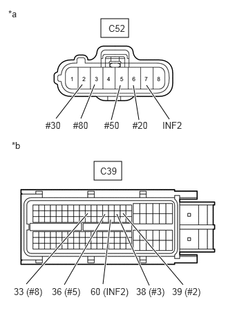
1.521,0.281 1.938,0.563 0.417,0.281 1.417,2.427 1.833,2.708 0.417,0.281 0.844,1.781 1.24,1.271 true 1.219,1.781 1.427,1.271 true 1.677,1.802 1.813,1.281 true 2.094,1.802 2.01,1.281 true 2.552,1.792 2.208,1.281 true 0.396,4.271 1.323,3.208 true 0.969,4.281 1.583,3.219 true 1.552,4.271 1.667,3.302 true 2.25,4.292 1.76,3.219 true 2.76,4.281 1.854,3.208 true 0.125,0.125 0.438,0.281 0.313,0.156 10 false *a 0.177,2.104 0.49,2.26 0.313,0.156 10 false *b 1.635,0.344 1.948,0.5 0.313,0.156 10 false C52 1.51,2.49 1.823,2.646 0.313,0.156 10 false C39 0.688,1.802 1,1.958 0.313,0.156 10 false #30 1.104,1.802 1.417,1.958 0.313,0.156 10 false #80 1.573,1.802 1.885,1.958 0.313,0.156 10 false #50 2,1.802 2.313,1.958 0.313,0.156 10 false #20 2.448,1.802 2.896,1.969 0.448,0.167 10 false INF2 0.208,4.302 0.698,4.458 0.49,0.156 10 false 33 (#8) 0.781,4.302 1.271,4.458 0.49,0.156 10 false 36 (#5) 1.365,4.302 1.938,4.469 0.573,0.167 10 false 60 (INF2) 2.052,4.302 2.615,4.458 0.563,0.156 10 false 38 (#3) 2.594,4.302 3.083,4.458 0.49,0.156 10 false 39 (#2)
*a Front view of wire harness connector
(to No. 2 EDU)
*b Front view of wire harness connector
(to ECM)


Disconnect the No. 2 EDU connector.


e.

Disconnect the ECM connector.


f.

Measure the resistance according to the value(s) in the table below.

Standard resistance:
No. 2
Tester Connection Condition Specified Condition
C52-6 (#20) - C39-39 (#2) Always Below 1 Ω
C52-2 (#30) - C39-38 (#3) Always Below 1 Ω
C52-5 (#50) - C39-36 (#5) Always Below 1 Ω
C52-3 (#80) - C39-33 (#8) Always Below 1 Ω
C52-7 (INF2) - C39-60(INF2) Always Below 1 Ω
C52-6 (#20) or C39-39 (#2) - Body ground Always 10 kΩ or higher
C52-2 (#30) or C39-38 (#3) - Body ground Always 10 kΩ or higher
C52-5 (#50) or C39-36 (#5) - Body ground Always 10 kΩ or higher
C52-3 (#80) or C39-33 (#8) - Body ground Always 10 kΩ or higher
C52-7 (INF2) or C39-60 (INF2) - Body ground Always 10 kΩ or higher


Result:
Proceed to
OK
NG


OK

4.INSPECT FUEL INJECTOR ASSEMBLY

NG

10.REPAIR OR REPLACE HARNESS OR CONNECTOR
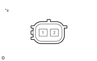
4.INSPECT FUEL INJECTOR ASSEMBLY
a.
A191333C24
1.885,1.083 2,1.229 0.115,0.146 10 false 2 1.479,1.083 1.594,1.229 0.115,0.146 10 false 1 0.177,0.281 0.458,0.531 0.281,0.25 10 false *a
*a Component without harness connected
(Fuel Injector)


Disconnect the fuel injector connectors.


b.

Measure the resistance according to the value(s) in the table below.

Standard resistance:
Tester Connection Condition Specified Condition
1 - 2 20°C (68°F) 0.85 to 1.05 Ω


Result:
Proceed to
OK
NG


OK

5.CHECK DTC

NG

9.REPLACE FUEL INJECTOR ASSEMBLY
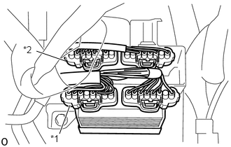
5.CHECK DTC
a.
A403502C01
0.885,1.99 1.042,1.563 true 0.542,0.76 0.969,0.906 true 0.344,0.656 0.656,0.854 0.313,0.198 10 false *2 0.75,1.979 1.063,2.177 0.313,0.198 10 false *1
*1 No. 1
*2 No. 2


Interchange the No. 1 and No. 2 EDU connectors.


b.

Connect the GTS to the DLC3.


c.

Turn the ignition switch ON and turn the GTS ON.


d.

Clear DTCs.

Powertrain > Engine and ECT > Clear DTCs
50002 61
NOTICE:

Before deleting the DTCs, write them down.


e.

Start the engine.


f.

Enter the following menus: Powertrain / Engine and ECT / Trouble Codes.

Powertrain > Engine and ECT > Trouble Codes
50001 61

g.

Read the DTCs.

Result:
Result Proceed to
DTCs do not change A
DTCs change (change in malfunctioning cylinder or EDU code) B


A

6.REPLACE ECM

B

8.REPLACE INJECTOR DRIVER
6.REPLACE ECM

Result:
Proceed to
NEXT


NEXT

7.CONFIRM CONFIRM WHETHER MALFUNCTION HAS BEEN SUCCESSFULLY REPAIRED
a.

Connect the GTS to the DLC3.


b.

Clear the DTCs.

Powertrain > Engine and ECT > Clear DTCs
50002 61

c.

Turn the ignition switch off.


d.

Start the engine and idle it for 10 seconds.


e.

Enter the following menus: Powertrain / Engine and ECT / Trouble Codes.

Powertrain > Engine and ECT > Trouble Codes
50001 61

f.

Confirm that the DTC is not output again.


Result:
Proceed to
NEXT


NEXT

END

8.REPLACE INJECTOR DRIVER
a.

Replace the injector driver.

Click hereEngine / Hybrid System>1VD-FTV (FUEL)>INJECTOR DRIVER>REMOVAL


Result:
Proceed to
NEXT


NEXT

7.CONFIRM CONFIRM WHETHER MALFUNCTION HAS BEEN SUCCESSFULLY REPAIRED
9.REPLACE FUEL INJECTOR ASSEMBLY
a.

Replace the fuel injector assembly.

Click hereEngine / Hybrid System>1VD-FTV (FUEL)>FUEL INJECTOR (w/o DPF)>REMOVAL


Result:
Proceed to
NEXT


NEXT

7.CONFIRM CONFIRM WHETHER MALFUNCTION HAS BEEN SUCCESSFULLY REPAIRED
10.REPAIR OR REPLACE HARNESS OR CONNECTOR
Result:
Proceed to
NEXT


NEXT

7.CONFIRM CONFIRM WHETHER MALFUNCTION HAS BEEN SUCCESSFULLY REPAIRED
11.GO TO INJECTOR CIRCUIT

Result:
Proceed to
NEXT


NEXT

7.CONFIRM CONFIRM WHETHER MALFUNCTION HAS BEEN SUCCESSFULLY REPAIRED