BRAKE CONTROL / DYNAMIC CONTROL SYSTEMS VEHICLE STABILITY CONTROL SYSTEM(w/ Pre-collision System) C050C12 Left Rear Wheel Speed Sensor Circuit Short to Battery C051212 Right Rear Wheel Speed Sensor Circuit Short to Battery
DESCRIPTION
Refer to DTCs C05001F and C05061F.
| DTC No. | Detection Item | DTC Detection Condition | Trouble Area |
|---|---|---|---|
| C050C12 | Left Rear Wheel Speed Sensor Circuit Short to Battery | The speed sensor short signal is ON continuously for 0.5 seconds or more. |
·
Rear speed sensor LH
·
Skid control ECU (Brake actuator assembly)
·
Skid control sensor wire
·
Wire harness or connector |
| C051212 | Right Rear Wheel Speed Sensor Circuit Short to Battery | The speed sensor short signal is ON continuously for 0.5 seconds or more. |
·
Rear speed sensor RH
·
Skid control ECU (Brake actuator assembly)
·
Skid control sensor wire
·
Wire harness or connector |
WIRING DIAGRAM
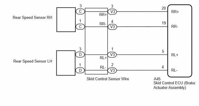
CAUTION / NOTICE / HINT
- NOTICE:
-
After replacing the skid control ECU (brake actuator assembly), perform "Calibration".
PROCEDURE
Disconnect the C or D rear speed sensor connector.
Turn the ignition switch to ON.
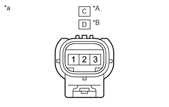
| *A | for RH |
| *B | for LH |
| *a | Front view of wire harness connector (to Rear Speed Sensor) |
Measure the voltage according to the value(s) in the table below.
- Standard Voltage:
-
for RH Tester Connection Switch Condition Specified Condition C-3 - C-1 Ignition switch ON 8 to 14 V
-
for LH Tester Connection Switch Condition Specified Condition D-3 - D-1 Ignition switch ON 8 to 14 V
- NOTICE:
-
Check the speed sensor signal after replacement.
- Result:
-
Proceed to OK NG
OK
NG
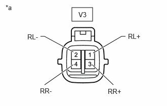
| *a | Front view of wire harness connector (to Skid Control Sensor Wire) |
Disconnect the V3 skid control sensor wire connector.
Turn the ignition switch to ON.
Measure the voltage according to the value(s) in the table below.
- Standard Voltage:
-
for RH Tester Connection Switch Condition Specified Condition V3-3 (RR+) - V3-4 (RR-) Ignition switch ON 8 to 14 V
-
for LH Tester Connection Switch Condition Specified Condition V3-1 (RL+) - V3-2 (RL-) Ignition switch ON 8 to 14 V
- NOTICE:
-
Check the speed sensor signal after replacement.
- Result:
-
Proceed to OK NG
OK
NG
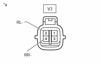
| *a | Front view of wire harness connector (to Skid Control Sensor Wire) |
Disconnect the A45 skid control ECU (brake actuator assembly) connector.
Measure the voltage according to the value(s) in the table below.
- Standard Voltage:
-
for RH Tester Connection Condition Specified Condition V3-4 (RR-) - Body ground Always Below 1.5 V
-
for LH Tester Connection Condition Specified Condition V3-2 (RL-) - Body ground Always Below 1.5 V
- Result:
-
Proceed to OK NG
OK
NG
| *A | for RH |
| *B | for LH |
| *a | Front view of wire harness connector (to Rear Speed Sensor) |
Measure the voltage according to the value(s) in the table below.
- Standard Voltage:
-
for RH Tester Connection Condition Specified Condition C-1 - Body ground Always Below 1.5 V
-
for LH Tester Connection Condition Specified Condition D-1 - Body ground Always Below 1.5 V
- Result:
-
Proceed to OK NG
OK
NG
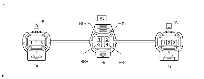
| *A | for RH | *B | for LH |
| *1 | Skid Control Sensor Wire | - | - |
| *a | Front view of wire harness connector (to Sensor Side Connector) |
*b | Front view of wire harness connector (to Vehicle Side Connector) |
Measure the resistance according to the value(s) in the table below.
- Standard Resistance:
-
for RH Tester Connection Condition Specified Condition V3-3 (RR+) or C-3 - V3-4 (RR-) or C-1 Always 10 kΩ or higher
-
for LH Tester Connection Condition Specified Condition V3-1 (RL+) or D-3 - V3-2 (RL-) or D-1 Always 10 kΩ or higher
- Result:
-
Proceed to OK NG
OK
NG
Measure the resistance according to the value(s) in the table below.
- Standard Resistance:
-
for RH Tester Connection Condition Specified Condition A45-20 (RR+) or V3-3 (RR+) - A45-19 (RR-) or V3-4 (RR-) Always 10 kΩ or higher
-
for LH Tester Connection Condition Specified Condition A45-5 (RL+) or V3-1 (RL+) - A45-4 (RL-) or V3-2 (RL-) Always 10 kΩ or higher
- Result:
-
Proceed to OK NG
OK
NG