1GR-FE COOLING WATER PUMP INSTALLATION
PROCEDURE

 16100 1.INSTALL ENGINE WATER PUMP ASSEMBLY
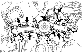

|
10 mm Head Bolt |

|
12 mm Head Bolt |
Install a new gasket and the engine water pump assembly with the 17 bolts.
- Torque:
- for 10 mm head bolt : 11 N*m (112 kgf*cm, 8 ft.*lbf)
- for 12 mm head bolt : 21 N*m (214 kgf*cm, 15 ft.*lbf)
16620 2.INSTALL V-RIBBED BELT TENSIONER ASSEMBLY
16631B 3.INSTALL IDLER PULLEY BRACKET (w/o Air Conditioning System)
Install the idler pulley assembly with the 3 bolts.
- Torque:
- 25 N*m (255 kgf*cm, 18 ft.*lbf)
88320 4.CONNECT COOLER COMPRESSOR ASSEMBLY (w/ Air Conditioning System)
27020 5.INSTALL GENERATOR ASSEMBLY
16604 6.INSTALL NO. 2 IDLER PULLEY SUB-ASSEMBLY
16323 7.INSTALL WATER INLET HOUSING
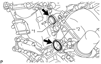
| *1 | No. 1 Water Outlet Pipe |
| *2 | Engine Water Pump Assembly |
Install a new gasket to the No. 1 water outlet pipe.
Install a new gasket to the engine water pump assembly.
Apply soapy water to the gasket of the No. 1 water outlet pipe.
Install the water inlet housing with the 5 bolts.
- Torque:
- 9.0 N*m (92 kgf*cm, 80 in.*lbf)
Connect the No. 3 water by-pass hose to the water inlet housing, and slide the clip to secure the hose.
Connect the water by-pass hose to the water inlet housing and union, and slide the 2 clips to secure the hoses.
Connect the No. 2 water by-pass hose to the water inlet housing, and slide the clip to secure the hose.
Connect the No. 4 water by-pass hose and No. 5 water by-pass hose to the water inlet housing, and slide the 2 clips to secure the hoses.
Connect the oil cooler hose and No. 2 oil cooler hose to the water inlet housing, and slide the 2 clips to secure the hoses.
16711 8.INSTALL FAN SHROUD
16572D 9.INSTALL NO. 2 RADIATOR HOSE
16571C 10.INSTALL NO. 1 RADIATOR HOSE
11.INSTALL AIR CLEANER CAP WITH AIR CLEANER HOSE
12.CONNECT CABLE TO NEGATIVE BATTERY TERMINAL
13. INITIALIZATION AFTER RECONNECTING BATTERY TERMINAL
- HINT:
-
When disconnecting and reconnecting the battery, there is an automatic learning function that completes learning when the respective system is used.
-
Click hereGeneral>SETUP>WHEN DISCONNECTING OR RECONNECTING BATTERY TERMINAL>AUTOMATIC LEARNING CHART
14.ADD ENGINE COOLANT
15.INSPECT FOR COOLANT LEAK
51442 16.INSTALL NO. 2 ENGINE UNDER COVER