Q710 HYBRID TRANSMISSION / TRANSAXLE MOTOR CABLE REMOVAL
CAUTION / NOTICE / HINT
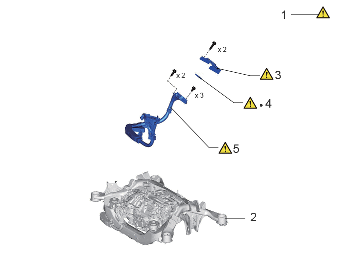
| Procedure | Part Name Code | 
|

|

|
|
|---|---|---|---|---|---|
| 1 | PRECAUTION | - | ( ) |
- | - |
| 2 | REAR SUSPENSION MEMBER SUB-ASSEMBLY | 51206A | - | - | - |
| 3 | CONNECTOR COVER | 82821T | ()
|
- | - |
| 4 | MOTOR CABLE TERMINAL CAP | G114D | ()
|
- | - |
| 5 | MOTOR CABLE | G1148 | ()
|
- | - |
| ● | Non-reusable part | - | - |
CAUTION / NOTICE / HINT
The necessary procedures (adjustment, calibration, initialization, or registration) that must be performed after parts are removed and installed, or replaced during motor cable removal/installation are shown below.
|
* The vehicle height changes because of suspension or tire replacement. |
|||
| Replaced Part or PerformedProcedure | Necessary Procedure | Effect/Inoperative Functionwhen Necessary Procedurenot Performed | Link |
| Auxiliary battery terminal isdisconnected/reconnected | Memorize steering angle neutral point | Parking assist monitor system | ()
|
| Panoramic view monitor system | ()
|
||
·
Rear disc (Including removal and installation) ·
Parking brake shoe (Including removal and installation) ·
Parking brake actuator assembly with bracket (Removed and installed) |
Parking brake bedding | Electric parking brake system | ()
|
| Suspension, tires, etc.* | ·
Measurement of ultrasonic sensor detection angle ·
Ultrasonic sensor detection angle registration |
·
Parking support brake system ·
Advanced park |
w/ Advanced Park:
( )
w/o Advanced Park: ( )
|
| Rear television camera assembly optical axis (Back camera position setting) | Parking assist monitor system | ()
|
|
·
Parking assist ECU initialization ·
Adjust sttering angle ·
Rear television camera view adjustment (for Rear camera detection system) |
Panoramic view monitor system | ()
|
|
| Perform headlight ECU sub-assembly LH initialization | Automatic headlight beam level control system | ()
|
|
| Rear wheel alignment adjustment | Electronically controlled brake system calibration | Electronically controlled brake system calibration | ()
|
- CAUTION:
- ·
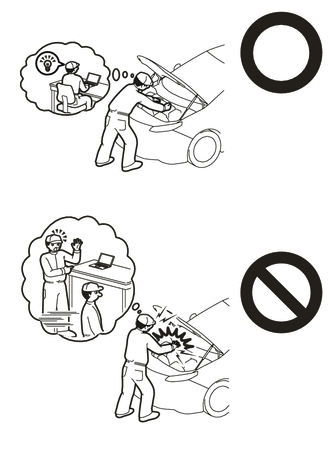
This vehicle has contains high voltage circuits standardized with orange colored wiring and connectors, so follow the instructions in this manual to perform the procedures correctly.
·If the correct procedures are not followed according to the instructions in this manual, there is a danger of electric shock from the high voltage circuits.
·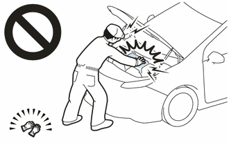
Be sure to wear insulating gloves when working on high voltage wiring or components.
·If work is performed without wearing insulating gloves, there is a danger of electric shock.
- HINT:
-
When the cable is disconnected/reconnected to the auxiliary battery terminal, systems temporarily stop operating. However, each system has a function that completes learning the first time the system is used.
- ·
Learning completes when vehicle is driven
Effect/Inoperative Function When Necessary Procedures are not Performed Necessary Procedures Link Lane tracing assist system Drive the vehicle straight ahead at 35 km/h (22 mph) or more for 5 seconds or more. ( )
Pre-collision system Adaptive high beam system
·Learning completes when vehicle is operated normally
Effect/Inoperative Function When Necessary Procedures are not Performed Necessary Procedures Link Air conditioning system After the ignition switch is turned to ON, theservo motor and expansion valve standardposition is recognized. -
PROCEDURE

 1. PRECAUTION
51206A
2.REMOVE REAR SUSPENSION MEMBER SUB-ASSEMBLY
82821T
3.REMOVE CONNECTOR COVER
|
|
|
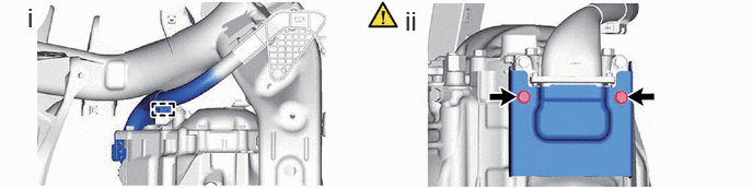
Detach the clamp.
Using an insulated tool, remove the 2 bolts and connector cover from the FCV with motor transaxle assembly.
G114D
4.REMOVE MOTOR CABLE TERMINAL CAP
|
|
|

G1148
5.REMOVE MOTOR CABLE
|
|
|
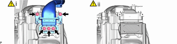
Using an insulated tool, remove the 5 bolts and motor cable from the FCV with motor transaxle assembly.
Cover the hole where the motor cable was installed with tape or equivalent (non-residue type) to prevent entry of foreign matter.