Q710 HYBRID TRANSMISSION / TRANSAXLE OIL COOLER INSTALLATION
CAUTION / NOTICE / HINT
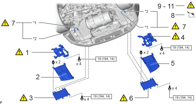
| Procedure | Part Name Code | 
|

|

|
|
|---|---|---|---|---|---|
| 1 | TRANSMISSION OIL COOLER BRACKET | 32913G | ( ) |
- | - |
| 2 | TRANSMISSION OIL COOLER AIR DUCT | 32917A | - | - | - |
| 3 | OIL COOLER ASSEMBLY | 32910L | ()
|
- | - |
| 4 | NO. 2 TRANSMISSION OIL COOLER BRACKET | 32913J | ()
|
- | - |
| 5 | TRANSMISSION OIL COOLER AIR DUCT LH | 32918B | - | - | - |
| 6 | OIL COOLER ASSEMBLY | 32910L | ()
|
- | - |
| 7 | OIL COOLER TUBE SUB-ASSEMBLY | 32906F | ()
|
- | - |
| 8 | ADD HYBRID TRANSAXLE FLUID | - | - | ()
|
- |
| 9 | BLEED AIR FROM HYBRID TRANSAXLE FLUID LINE | - | ()
|
- | - |
| 10 | INSPECT HYBRID TRANSAXLE FLUID | - | ()
|
- | - |
| 11 | INSPECT FOR HYBRID TRANSAXLE FLUID LEAK | - | ()
|
- | - |
| *1 | OIL COOLER INLET HOSE | *2 | OIL COOLER OUTLET HOSE |

|
N*m (kgf*cm, ft.*lbf): Specified torque | - | - |
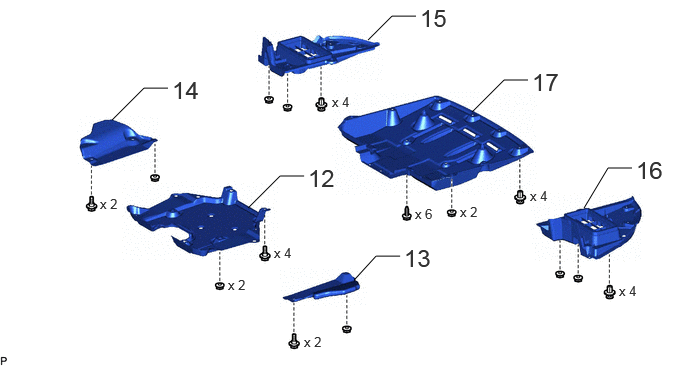
| Procedure | Part Name Code |
|
|
|
|
|---|---|---|---|---|---|
| 12 | REAR SUSPENSION BRACE COVER | 53661B | - | - | - |
| 13 | NO. 2 DIFFERENTIAL SUPPORT PROTECTOR | 52384C | - | - | - |
| 14 | NO. 1 DIFFERENTIAL SUPPORT PROTECTOR | 52383E | - | - | - |
| 15 | TRANSMISSION OIL COOLER UNDER COVER RH | 32911 | - | - | - |
| 16 | TRANSMISSION OIL COOLER UNDER COVER LH | 32912B | - | - | - |
| 17 | NO. 1 FLOOR UNDER COVER | 58398F | - | - | - |
PROCEDURE

 32913G
1.INSTALL TRANSMISSION OIL COOLER BRACKET
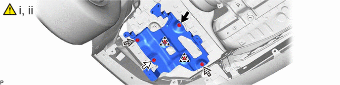

|
Bolt A | 
|
Bolt B |

|
Bolt C | 
|
Bolt D |
Temporarily install the transmission oil cooler bracket to the vehicle body with the 2 clips.
Install the transmission oil cooler bracket to the vehicle body with the 4 bolts.
- Torque:
- 19 N*m (194 kgf*cm, 14 ft.*lbf)
- HINT:
-
Tightening order: Temporarily install bolt A → Temporarily install bolt B → Temporarily install bolt C and bolt D → Tighten bolt A → Tighten bolt B → Tighten bolt C and bolt D
32917A
2.INSTALL TRANSMISSION OIL COOLER AIR DUCT
32910L
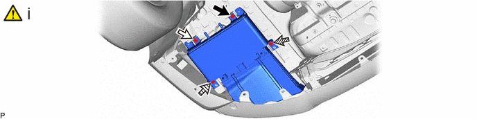
3.INSTALL OIL COOLER ASSEMBLY
|
|
|
|
|
Bolt A |
|
Bolt B |
|
|
Bolt C |
|
Bolt D |
Install the oil cooler assembly to the vehicle body with the 4 bolts.
- Torque:
- 19 N*m (194 kgf*cm, 14 ft.*lbf)
- HINT:
-
Tightening order: Temporarily install bolt A → Temporarily install bolt B → Temporarily install bolt C and bolt D → Tighten bolt A → Tighten bolt B → Tighten bolt C and bolt D
32913J
4.INSTALL NO. 2 TRANSMISSION OIL COOLER BRACKET
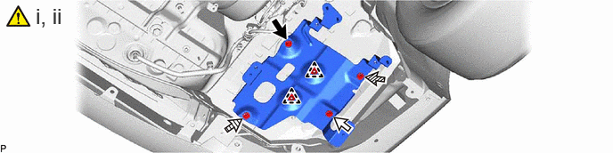
|
|
Bolt A |
|
Bolt B |
|
|
Bolt C |
|
Bolt D |
Temporarily install the No. 2 transmission oil cooler bracket to the vehicle body with the 2 clips.
Install the No. 2 transmission oil cooler bracket to the vehicle body with the 4 bolts.
- Torque:
- 19 N*m (194 kgf*cm, 14 ft.*lbf)
- HINT:
-
Tightening order: Temporarily install bolt A → Temporarily install bolt B → Temporarily install bolt C and bolt D → Tighten bolt A → Tighten bolt B → Tighten bolt C and bolt D
32918B
5.INSTALL TRANSMISSION OIL COOLER AIR DUCT LH
32910L
6.INSTALL OIL COOLER ASSEMBLY
|
|
|
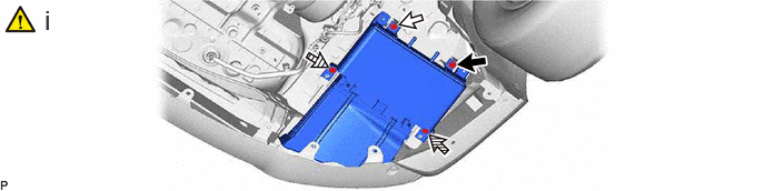
|
|
Bolt A |
|
Bolt B |
|
|
Bolt C |
|
Bolt D |
Install the oil cooler assembly to the vehicle body with the 4 bolts.
- Torque:
- 19 N*m (194 kgf*cm, 14 ft.*lbf)
- HINT:
-
Tightening order: Temporarily install bolt A → Temporarily install bolt B → Temporarily install bolt C and bolt D → Tighten bolt A → Tighten bolt B → Tighten bolt C and bolt D
32906F
7.CONNECT OIL COOLER TUBE SUB-ASSEMBLY
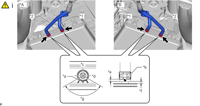
| *A | Right Side of Vehicle | *B | Left Side of Vehicle |
| *1 | Oil Cooler Tube Sub-assembly (Oil Cooler Inlet Hose) | *2 | Oil Cooler Tube Sub-assembly (Oil Cooler Outlet Hose) |
| *a | Oil Cooler Marking | *b | Hose Marking |
| *c | Upper Side of Vehicle | *d | Left Side of Vehicle |
| *e | 4 to 7 mm (0.158 to 0.275 in.) | *f | 2 to 4 mm (0.0788 to 0.158 in.) |
| *g | 120°(Claw of Clip Location) | - | - |
Connect the oil cooler tube sub-assembly (oil cooler inlet hose) and oil cooler tube sub-assembly (oil cooler outlet hose) to the 2 oil cooler assemblies, and slide the 4 clips to secure them.
- NOTICE:
- ·
Make sure to align the hose marking of the oil cooler inlet hose and oil cooler outlet hose with the oil cooler marking of the oil cooler assembly.
·Make sure that the claws of the clip are within the location shown in the illustration.
8.ADD HYBRID TRANSAXLE FLUID
|
|
Click here()
|
9.BLEED AIR FROM HYBRID TRANSAXLE FLUID LINE
|
|
Click here()
|
10.INSPECT HYBRID TRANSAXLE FLUID
|
|
Click here()
|
11.INSPECT FOR HYBRID TRANSAXLE FLUID LEAK
|
|
Click here()
|
53661B
12.INSTALL REAR SUSPENSION BRACE COVER
52384C
13.INSTALL NO. 2 DIFFERENTIAL SUPPORT PROTECTOR
52383E
14.INSTALL NO. 1 DIFFERENTIAL SUPPORT PROTECTOR
32911
15.INSTALL TRANSMISSION OIL COOLER UNDER COVER RH
32912B
16.INSTALL TRANSMISSION OIL COOLER UNDER COVER LH
58398F
17.INSTALL NO. 1 FLOOR UNDER COVER