SUPPLEMENTAL RESTRAINT SYSTEMS POP UP HOOD SENSOR REMOVAL
CAUTION / NOTICE / HINT
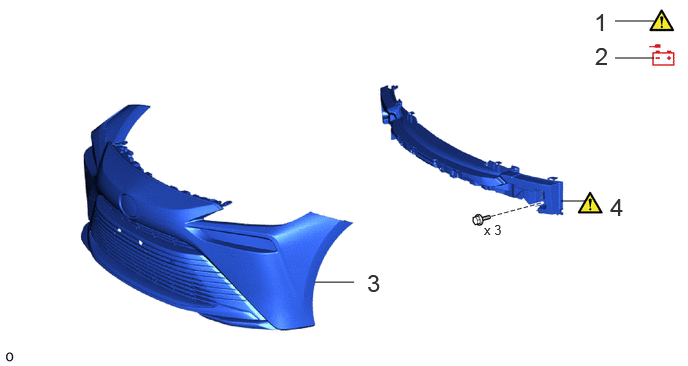
| Procedure | Part Name Code | 
|

|

|
|
|---|---|---|---|---|---|
| 1 | PRECAUTION | - | ( ) |
- | - |
| 2 | DISCONNECT CABLE FROM NEGATIVE AUXILIARY BATTERY TERMINAL | - | ()
|
- | - |
| 3 | FRONT BUMPER ASSEMBLY | - | - | - | - |
| 4 | FRONT BUMPER ENERGY ABSORBER SUB-ASSEMBLY | - | - | - | - |
| Procedure | Part Name Code |
|
|
|
|
|---|---|---|---|---|---|
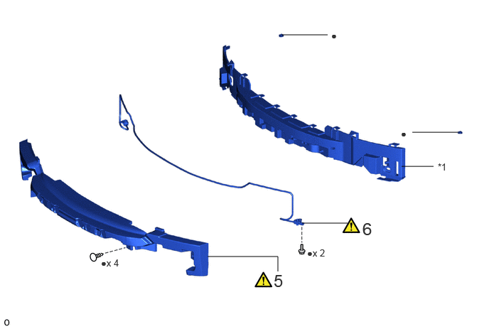
| 5 | FRONT BUMPER ENERGY ABSORBER | 52611 | ()
|
- | - |
| 6 | PEDESTRIAN DETECTION CHAMBER ASSEMBLY | 52620 | ()
|
- | - |
| *1 | NO. 2 FRONT BUMPER MOUNTING BRACKET | - | - |
| ● | Non-reusable part | - | - |
CAUTION / NOTICE / HINT
The necessary procedures (adjustment, calibration, initialization or registration) that must be performed after parts are removed, installed or replaced during the pedestrian detection chamber assembly removal/installation are shown below.
| Replaced Part or Performed Procedures | Necessary Procedures | Effect/Inoperative Function when Necessary Procedures are not Performed | Link |
|---|---|---|---|
| Disconnect cable from negative (-) auxiliary battery terminal | Memorize steering angle neutral point | Parking assist monitor system | ()
|
| Panoramic View Monitor System | ()
|
||
| Front bumper assembly (Including removal and installation) | ·
Measurement of ultrasonic sensor detection angle ·
Ultrasonic sensor detection angle registration |
·
TOYOTA Parking assist- sensor system ·
Parking support brake system ·
Advanced park |
w/ Advanced Park:
( )
w/o Advanced Park: ( )
|
| Front television camera view adjustment | Panoramic view monitor system | ()
|
- HINT:
-
When the cable is disconnected/reconnected to the auxiliary battery terminal, systems temporarily stop operating. However, each system has a function that completes learning the first time the system is used.
- ·
Learning completes when vehicle is driven
Effect/Inoperative Function When Necessary Procedures are not Performed Necessary Procedures Link Lane tracing assist system Drive the vehicle straight ahead at 35 km/h (22 mph) or more for 5 seconds or more. ( )
Pre-collision system Adaptive high beam system
·Learning completes when vehicle is operated normally
Effect/Inoperative Function When Necessary Procedures are not Performed Necessary Procedures Link Air conditioning system After the ignition switch is turned to ON, the servo motor and expansion valve standard position is recognized. -
PROCEDURE

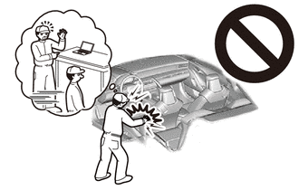
 1. PRECAUTION
|
|
|
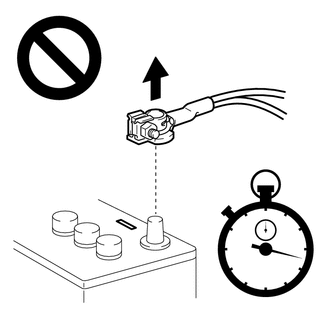
2.DISCONNECT CABLE FROM NEGATIVE AUXILIARY BATTERY TERMINAL
|
|
|
3.REMOVE FRONT BUMPER ASSEMBLY
4.REMOVE FRONT BUMPER ENERGY ABSORBER SUB-ASSEMBLY
52611
5.REMOVE FRONT BUMPER ENERGY ABSORBER
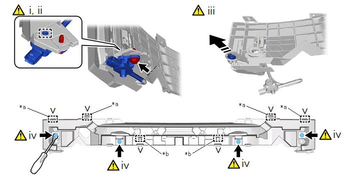
Remove the Bolt.
- HINT:
-
Use the same procedure for the opposite side.
Detch the guide and remove the pedestrian protection sensor from the front energy absorber mounting reinforcement.
- NOTICE:
- ·
When inspect the pedestrian detection chamber assembly, do not remove the pedestrian protection sensor.
·Do not subject the pedestrian detection chamber assembly to any strong impact (such as dropping).
·If the pedestrian protection sensor is subjected to any strong impact, replace the pedestrian detection chamber assembly with a new one.
·Hold the pedestrian protection sensor so as not to damage the front energy absorber mounting reinforcement RH.
·Do not pull only pedestrian protection sensor.
·Do not pull only pedestrian detection chamber.
·Do not reuse the bolt.
- HINT:
-
Use the same procedure for the opposite side.
Remove the nut.
- HINT:
-
Use the same procedure for the opposite side.
Using a clip remover, remove the 4 clips.
- HINT:
-
Tape the clip remover tip before use.
Detach the hook and guide and remove the front energy absorber from the No. 2 front bumper mounting bracket.
52620
6.REMOVE PEDESTRIAN DETECTION CHAMBER ASSEMBLY
|
|
|
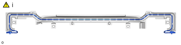
Remove the pedestrian detection chamber from the pedestrian detection chamber connection area of the front bumper energy absorber.
- NOTICE:
- ·
Do not pull only pedestrian protection sensor.
·Do not pull only pedestrian detection chamber.
·Do not damage the pedestrian detection chamber connection area of the front bumper energy absorber.
·If a pedestrian detection chamber connection area is damaged, replace the front bumper energy absorber with a new one.