INTERIOR PANELS / TRIM INSTRUMENT PANEL SAFETY PAD INSTALLATION
CAUTION / NOTICE / HINT
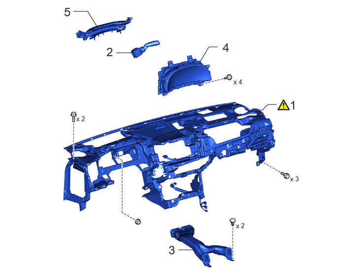
| Procedure | Part Name Code | 
|

|

|
|
|---|---|---|---|---|---|
| 1 | INSTRUMENT PANEL SAFETY PAD ASSEMBLY | - | ( ) |
- | - |
| 2 | WINDSHIELD WIPER SWITCH ASSEMBLY | 84650 | - | - | - |
| 3 | NO. 1 CONSOLE BOX DUCT | 58861B | - | - | - |
| 4 | COMBINATION METER ASSEMBLY | 83100 | - | - | - |
| 5 | LOWER INSTRUMENT COVER SUB-ASSEMBLY | 55407C | - | - | - |
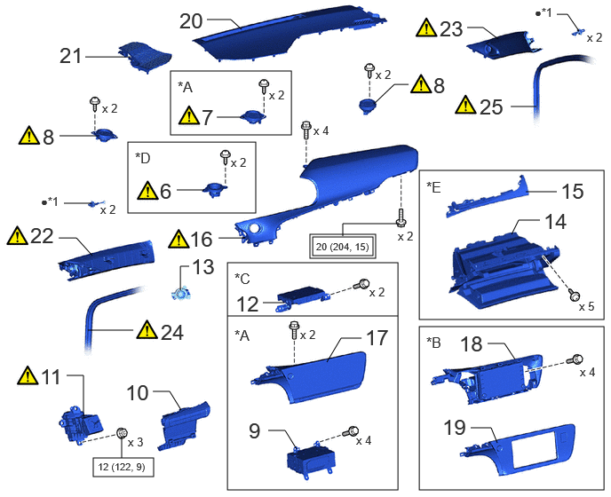
| Procedure | Part Name Code |
|
|
|
|
|---|---|---|---|---|---|
| 6 | NO. 4 SPEAKER WITH BOX ASSEMBLY | 86150D | ()
|
- | - |
| 7 | FRONT NO. 3 SPEAKER ASSEMBLY | 86160J | ()
|
- | - |
| 8 | FRONT NO. 2 SPEAKER ASSEMBLY | 86160P | ()
|
- | - |
| 9 | RADIO RECEIVER ASSEMBLY WITH BRACKET | - | - | - | - |
| 10 | AIR CONDITIONING CONTROL ASSEMBLY | 55900 | - | - | - |
| 11 | SHIFT LOCK CONTROL UNIT ASSEMBLY | 33560 | ()
|
- | - |
| 12 | NAVIGATION ECU ASSEMBLY WITH BRACKET | - | - | - | - |
| 13 | POWER SWITCH | 89611 | - | - | - |
| 14 | GLOVE COMPARTMENT DOOR ASSEMBLY | 55550 | - | - | - |
| 15 | LOWER INSTRUMENT CLUSTER FINISH PANEL GARNISH | 55479D | - | - | - |
| 16 | NO. 2 INSTRUMENT PANEL SAFETY PAD SUB-ASSEMBLY | 55403E | ()
|
- | - |
| 17 | MULTI-DISPLAY ASSEMBLY WITH BRACKET | - | - | - | - |
| 18 | RADIO AND DISPLAY RECEIVER ASSEMBLY WITH BRACKET | - | - | - | - |
| 19 | CENTER INSTRUMENT CLUSTER FINISH PANEL SUB-ASSEMBLY | 55405B | - | - | - |
| 20 | NO. 1 INSTRUMENT PANEL SPEAKER PANEL | 55472C | - | - | - |
| 21 | NO. 2 INSTRUMENT PANEL SPEAKER PANEL | 55473B | - | - | - |
| 22 | FRONT PILLAR GARNISH ASSEMBLY LH | 62212B | ()
|
- | - |
| 23 | FRONT PILLAR GARNISH ASSEMBLY RH | 62211U | ()
|
- | - |
| 24 | FRONT DOOR OPENING TRIM WEATHERSTRIP LH | 62312B | ()
|
- | - |
| 25 | FRONT DOOR OPENING TRIM WEATHERSTRIP RH | 62311B | ()
|
- | - |
| *A | for 14 Speakers | *B | for 6 Speakers |
| *C | w/ Navigation System | *D | w/ Telematics Transceiver |
| *E | for LHD | - | - |
| *1 | FRONT PILLAR GARNISH CLIP | - | - |

|
Tightening torque for "Major areas involving basic vehicle performance such as moving/turning/stopping": N*m (kgf*cm, ft.*lbf) | 
|
N*m (kgf*cm, ft.*lbf): Specified torque |
| ● | Non-reusable part | - | - |
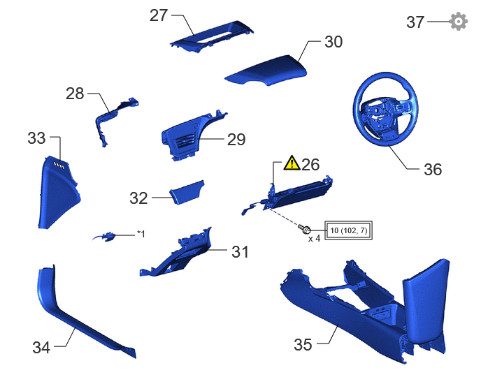
| Procedure | Part Name Code |
|
|
|
|
|---|---|---|---|---|---|
| 26 | LOWER NO. 1 INSTRUMENT PANEL AIRBAG ASSEMBLY | 73900 | ()
|
- | - |
| 27 | INSTRUMENT CLUSTER FINISH PANEL END | 55414A | - | - | - |
| 28 | INSTRUMENT PANEL FINISH PLATE | 55445B | - | - | - |
| 29 | INSTRUMENT CLUSTER FINISH PANEL SUB-ASSEMBLY | 55404D | - | - | - |
| 30 | INSTRUMENT CLUSTER FINISH PANEL ASSEMBLY | 55410C | - | - | - |
| 31 | LOWER INSTRUMENT PANEL FINISH PANEL SUB-ASSEMBLY | 55045 | - | - | - |
| 32 | INSTRUMENT CLUSTER FINISH PANEL ORNAMENT | 55471A | - | - | - |
| 33 | NO. 1 INSTRUMENT SIDE PANEL | 55317E | - | - | - |
| 34 | FRONT DOOR SCUFF PLATE LH | 67914B | - | - | - |
| 35 | CONSOLE BOX ASSEMBLY | 58810J | - | - | - |
| 36 | STEERING WHEEL ASSEMBLY | 45100 | - | - | - |
| 37 | INITIALIZATION AFTER RECONNECTING AUXILIARY BATTERY TERMINAL | - | - | - | ()
|
| *1 | HOOD LOCK CONTROL LEVER SUB-ASSEMBLY | - | - |
|
|
Tightening torque for "Major areas involving basic vehicle performance such as moving/turning/stopping": N*m (kgf*cm, ft.*lbf) | - | - |
- HINT:
- ·
Use the same procedure for RHD and LHD vehicles.
·The procedure listed below is for LHD vehicles.
PROCEDURE

 1.INSTALL INSTRUMENT PANEL SAFETY PAD ASSEMBLY
When installing a new instrument panel safety pad assembly:
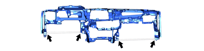
Immediately before installing the instrument panel safety pad sub-assembly, twist and cut off the portion as shown in the illustration.
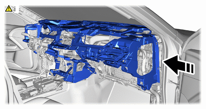

|
Install in this Direction | - | - |
Insert the instrument panel safety pad assembly into the vehicle as shown in the illustration to set it.
- NOTICE:
- ·
Do not damage the instrument panel safety pad assembly or vehicle interior.
·Make sure that the wire harness does not get caught on anything as it may become damaged.
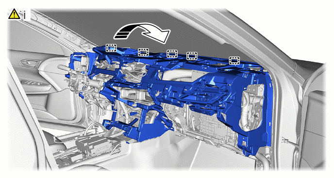
|
|
Install in this Direction | - | - |
Lift in the direction indicated by the arrow shown in the illustration and insert the guide.
- NOTICE:
- ·
Do not damage the instrument panel safety pad assembly or vehicle interior.
·Make sure that the wire harness does not get caught on anything as it may become damaged.
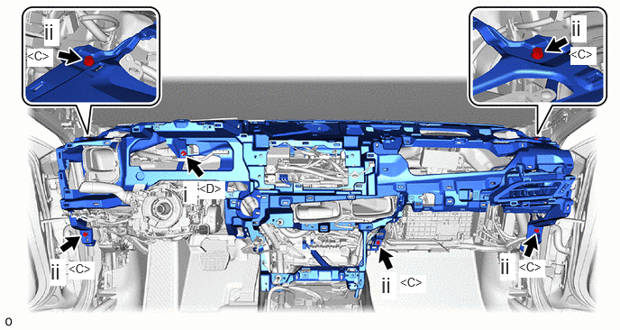
Install the nut <D>.
Install the 5 bolts <C>.
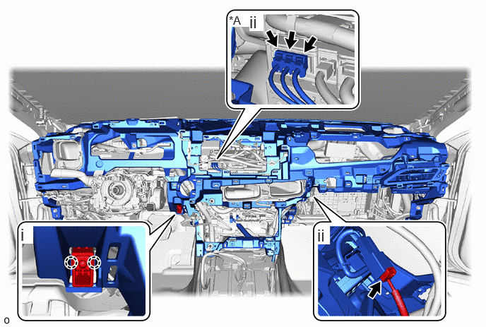
| *A | w/ Telematics Transceiver | - | - |
Attach the claw and connect the cooler thermistor (room temperature sensor).
Connect each connector.
84650
2.INSTALL WINDSHIELD WIPER SWITCH ASSEMBLY
58861B
3.INSTALL NO. 1 CONSOLE BOX DUCT
83100
4.INSTALL COMBINATION METER ASSEMBLY
55407C
5.INSTALL LOWER INSTRUMENT COVER SUB-ASSEMBLY
86150D
6.INSTALL NO. 4 SPEAKER WITH BOX ASSEMBLY (w/ Telematics Transceiver)
|
|
Click here()
|
86160J
7.INSTALL FRONT NO. 3 SPEAKER ASSEMBLY (for 14 Speakers)
|
|
Click here()
|
86160P
8.INSTALL FRONT NO. 2 SPEAKER ASSEMBLY
|
|
Click here()
|
9.INSTALL RADIO RECEIVER ASSEMBLY WITH BRACKET (for 14 Speakers)
55900
10.INSTALL AIR CONDITIONING CONTROL ASSEMBLY
33560
11.INSTALL SHIFT LOCK CONTROL UNIT ASSEMBLY
|
|
Click here()
|
12.INSTALL NAVIGATION ECU ASSEMBLY WITH BRACKET (w/ Navigation System)
89611
13.INSTALL POWER SWITCH
55550
14.INSTALL GLOVE COMPARTMENT DOOR ASSEMBLY (for LHD)
55479D
15.INSTALL LOWER INSTRUMENT CLUSTER FINISH PANEL GARNISH (for LHD)
55403E
16.INSTALL NO. 2 INSTRUMENT PANEL SAFETY PAD SUB-ASSEMBLY
|
|
Click here()
|
17.INSTALL MULTI-DISPLAY ASSEMBLY WITH BRACKET (for 14 Speakers)
18.INSTALL RADIO AND DISPLAY RECEIVER ASSEMBLY WITH BRACKET (for 6 Speakers)
55405B
19.INSTALL CENTER INSTRUMENT CLUSTER FINISH PANEL SUB-ASSEMBLY (for 6 Speakers)
55472C
20.INSTALL NO. 1 INSTRUMENT PANEL SPEAKER PANEL
55473B
21.INSTALL NO. 2 INSTRUMENT PANEL SPEAKER PANEL
62212B
22.INSTALL FRONT PILLAR GARNISH ASSEMBLY LH

| *a | Protective Cover | - | - |

|
Adhesive Tape | - | - |
Peel off the adhesive tape and remove the protective cover.
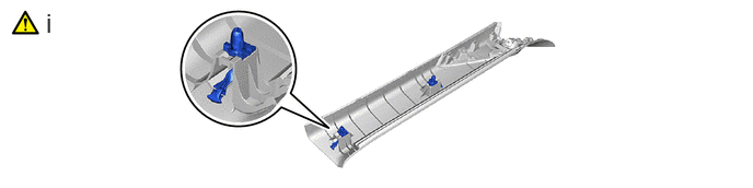
Install the 2 new front pillar garnish clips to the front pillar garnish LH.
- NOTICE:
-
Make sure that the position and direction of the front pillar garnish clip is correct when installing.
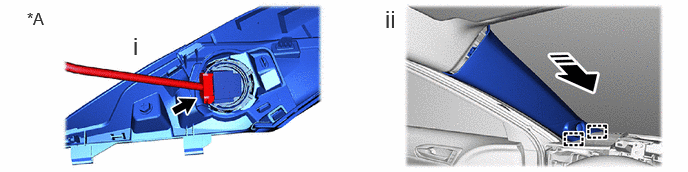
| *A | for 14 Speakers | - | - |
|
|
Install in this Direction | - | - |
for 14 Speakers:
1. Connect the connector.
Attach the guide as shown in the illustration.
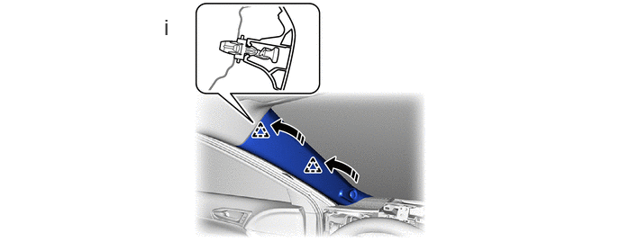
|
|
Install in this Direction | - | - |
Attach the front pillar garnish clip as shown in the illustration to install the front pillar garnish assembly LH.
- HINT:
-
Make sure that the curtain shield airbag assembly LH is not pinched.
62211U
23.INSTALL FRONT PILLAR GARNISH ASSEMBLY RH
Use the same procedure described for the LH side.
62312B
24.INSTALL FRONT DOOR OPENING TRIM WEATHERSTRIP LH
|
|
Click here()
|
62311B
25.INSTALL FRONT DOOR OPENING TRIM WEATHERSTRIP RH
Use the same procedure described for the LH side.
73900
26.INSTALL LOWER NO. 1 INSTRUMENT PANEL AIRBAG ASSEMBLY
|
|
Click here()
|
55414A
27.INSTALL INSTRUMENT CLUSTER FINISH PANEL END
55445B
28.INSTALL INSTRUMENT PANEL FINISH PLATE
55404D
29.INSTALL INSTRUMENT CLUSTER FINISH PANEL SUB-ASSEMBLY
55410C
30.INSTALL INSTRUMENT CLUSTER FINISH PANEL ASSEMBLY
55045
31.INSTALL LOWER INSTRUMENT PANEL FINISH PANEL SUB-ASSEMBLY
55471A
32.INSTALL INSTRUMENT CLUSTER FINISH PANEL ORNAMENT
55317E
33.INSTALL NO. 1 INSTRUMENT SIDE PANEL
67914B
34.INSTALL FRONT DOOR SCUFF PLATE LH
58810J
35.INSTALL CONSOLE BOX ASSEMBLY
45100
36.INSTALL STEERING WHEEL ASSEMBLY
37. INITIALIZATION AFTER RECONNECTING AUXILIARY BATTERY TERMINAL
Click hereGeneral>SETUP>WHEN DISCONNECTING OR RECONNECTING BATTERY TERMINAL>WORK PROCEDURE
- HINT:
-
When disconnecting and reconnecting the auxiliary battery, there is an automatic learning function that completes learning when the respective system is used.
-
Click hereGeneral>SETUP>WHEN DISCONNECTING OR RECONNECTING BATTERY TERMINAL>AUTOMATIC LEARNING CHART