EXTERIOR PANELS / TRIM FRONT FENDER DISASSEMBLY
CAUTION / NOTICE / HINT
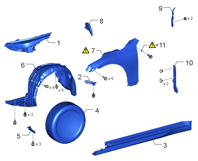
| Procedure | Part Name Code | 
|

|

|
|
|---|---|---|---|---|---|
| 1 | HEADLIGHT ASSEMBLY LH | - | - | - | - |
| 2 | FRONT BUMPER SIDE SUPPORT LH | 52116A | - | - | - |
| 3 | ROCKER PANEL MOULDING ASSEMBLY LH | - | - | - | - |
| 4 | WHEEL ASSEMBLY | - | - | - | - |
| 5 | FRONT WHEEL OPENING EXTENSION PAD LH | 53852B | - | - | - |
| 6 | FRONT FENDER SPLASH SHIELD SUB-ASSEMBLY LH | 53806C | - | - | - |
| 7 | FRONT FENDER SUB-ASSEMBLY LH | 53802 | ( ) |
- | - |
| 8 | FRONT SIDE AIR GUIDE | 53153E | - | - | - |
| 9 | FRONT FENDER SIDE PANEL PROTECTOR LH | 53828K | - | - | - |
| 10 | FRONT SIDE PANEL NO. 2 PROTECTOR LH | 53824B | - | - | - |
| 11 | FRONT FENDER SEAL LH | 53883B | ()
|
- | - |
| ● | Non-reusable part | - | - |
CAUTION / NOTICE / HINT
The necessary procedures (adjustment, calibration, initialization or registration) that must be performed after parts are removed, installed or replaced during the front fender sub-assembly disassembly/reassembly are shown below.
| Replaced Part or Performed Procedures | Necessary Procedures | Effect/Inoperative Function when Necessary Procedures are not Performed | Link |
|---|---|---|---|
| Disconnect cable from negative (-) auxiliary battery terminal | Memorize steering angle neutral point | Parking assist monitor system | ()
|
| Panoramic view monitor system | ()
|
||
| Ultrasonic sensor (Including removal and installation) | ·
Measurement of ultrasonic sensor detection angle ·
Ultrasonic sensor detection angle registration |
·
TOYOTA Parking assist- sensor system ·
Parking support brake system ·
Advanced park |
w/ Advanced Park:
( )
w/o Advanced Park: ( )
|
·
Front bumper assembly (Including removal and installation) ·
Radiator grille assembly (Including removal and installation) |
·
Measurement of ultrasonic sensor detection angle ·
Ultrasonic sensor detection angle registration |
||
| Front television camera view adjustment | Panoramic view monitor system | ()
|
|
| Front television camera assembly (Including removal and installation) | Front television camera view adjustment | Panoramic view monitor system | ()
|
| Front television camera assembly, front bumper assembly or radiator grille | ·
Television camera view adjustment
|
Panoramic view monitor system |
- HINT:
- ·
When the cable is disconnected/reconnected to the auxiliary battery terminal, systems temporarily stop operating. However, each system has a function that completes learning the first time the system is used.
-Learning completes when vehicle is driven
Effect/Inoperative Function When Necessary Procedures are not Performed Necessary Procedures Link Lane tracing assist system Drive the vehicle straight ahead at 35 km/h (22 mph) or more for 5 seconds or more. ( )
Pre-collision system Adaptive high beam system
-Learning completes when vehicle is operated normally
Effect/Inoperative Function When Necessary Procedures are not Performed Necessary Procedures Link Air conditioning system After the ignition switch is turned to ON, the servo motor and expansion valve standard position is recognized. -
·Use the same procedure for the RH and LH sides.
·The procedure described below is for the LH side.
PROCEDURE

 1.REMOVE HEADLIGHT ASSEMBLY LH
52116A
2.REMOVE FRONT BUMPER SIDE SUPPORT LH
3.REMOVE ROCKER PANEL MOULDING ASSEMBLY LH
4.REMOVE WHEEL ASSEMBLY
53852B
5.REMOVE FRONT WHEEL OPENING EXTENSION PAD LH
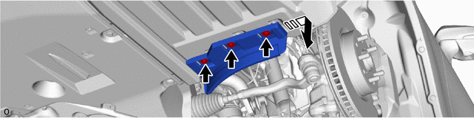

|
Remove in this Direction | - | - |
53806C
6.REMOVE FRONT FENDER SPLASH SHIELD SUB-ASSEMBLY LH
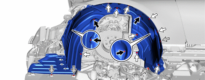

|
Screw<A> | 
|
Clip<A> |

|
Clip<B> | 
|
Screw<B> |
53802
7.REMOVE FRONT FENDER SUB-ASSEMBLY LH
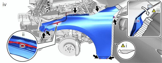
|
|
Bolt |
|
Fold Back |
Put protective tape around the front fender sub-assembly LH.
Detach the clamp.
Detach the guide and fold back the front fender side panel protector LH.
Remove the 7 bolts and front fender sub-assembly LH.
53153E
8.REMOVE FRONT SIDE AIR GUIDE
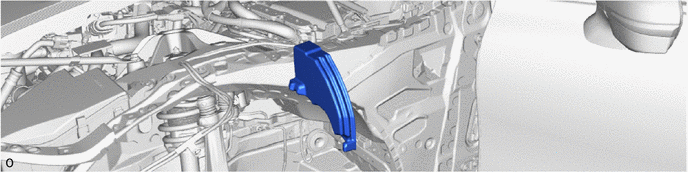
53828K
9.REMOVE FRONT FENDER SIDE PANEL PROTECTOR LH
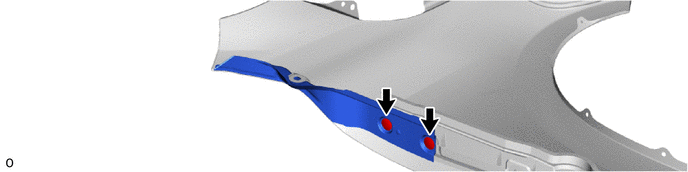
53824B
10.REMOVE FRONT SIDE PANEL NO. 2 PROTECTOR LH
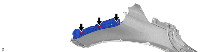
53883B
11.REMOVE FRONT FENDER SEAL LH
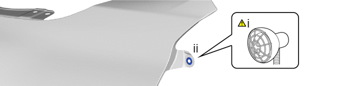
Heat the adhesive of the front fender seal LH using a heat light.
- Standard Value:
Part Temperature Front Fender Seal LH 20 to 30°C (68 to 86°F)
- CAUTION:
-
 2.365,2 2.698,2 false 0.5,2.333 0.5,2.667 true 0.427,2.708 0.74,2.865 0.313,0.156 10 false *a 2.76,1.927 3.073,2.083 0.313,0.156 10 false *b
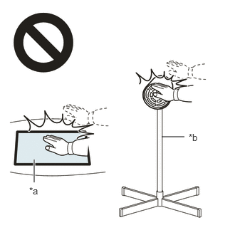
*a Heated Part *b Heat Light
- ·
Do not touch the heat light and heated parts.
·Touching the heat light may result in burns.
·Touching heated parts for a long time may result in burns.
- NOTICE:
-
Do not heat the front fender seal LH excessively.
Remove the front fender seal LH.