LIGHTING (EXT) LIGHTING SYSTEM Stop Light Circuit
DESCRIPTION
The illumination of the stop lights is controlled by release signals sent to the No. 2 semiconductor power integration ECU from the stop light switch assembly.
WIRING DIAGRAM
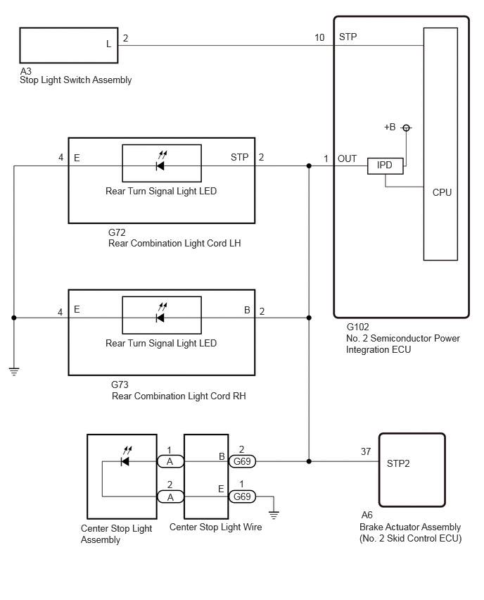
CAUTION / NOTICE / HINT
- NOTICE:
- ·
First, confirm that there is no malfunction in the power integration system. Refer to the How to Proceed with Troubleshooting procedure.
·First, confirm that there is no malfunction in the electronically controlled brake system. Refer to the How to Proceed with Troubleshooting procedure.
·After the ignition switch is turned off, there may be a waiting time before disconnecting the negative (-) auxiliary battery terminal.
Click hereGeneral>SETUP>WHEN DISCONNECTING OR RECONNECTING BATTERY TERMINAL>BEFORE DISCONNECTING BATTERY
·When disconnecting and reconnecting the auxiliary battery.
Click hereGeneral>SETUP>WHEN DISCONNECTING OR RECONNECTING BATTERY TERMINAL>WORK PROCEDURE
- HINT:
-
When disconnecting and reconnecting the auxiliary battery, there is an automatic learning function that completes learning when the respective system is used.
-
Click hereGeneral>SETUP>WHEN DISCONNECTING OR RECONNECTING BATTERY TERMINAL>AUTOMATIC LEARNING CHART
PROCEDURE
Depress the brake pedal.
Using the GTS, read the Data List.
- Body Electrical > Power Integration No.3 > Data List
-
Tester Display Measurement Item Range Normal Condition Diagnostic Note Stop Light Input Signal Stop light switch assembly input signal OFF or ON OFF: Brake pedal released
ON: Brake pedal depressed-
- Body Electrical > Power Integration No.3 > Data List
-
Tester Display Stop Light Input Signal - 50003 412 68
- OK:
Display changes according to the brake pedal operation.
- Result:
Proceed to OK NG
OK
NG
Depress the brake pedal.
Using the GTS, read the Data List.
- Body Electrical > Power Integration No.3 > Data List
-
Tester Display Measurement Item Range Normal Condition Diagnostic Note Stop Light Output Signal Stop light output condition OFF or ON OFF: Stop light is off
ON: Stop light is onStop lights blink during emergency brake signal control
- Body Electrical > Power Integration No.3 > Data List
-
Tester Display Stop Light Output Signal - 50003 412 76
- OK:
Display changes according to the brake pedal operation.
- Result:
Proceed to OK NG
OK
NG
Depress the brake pedal.
Using the GTS, read the Data List.
- Body Electrical > Power Integration No.3 > Data List
-
Tester Display Measurement Item Range Normal Condition Diagnostic Note Status of Stop Light Fuse Stop light fuse Connect or Disconnect Connect: Fuse not shut off
Disconnect: Fuse shut off-
- Body Electrical > Power Integration No.3 > Data List
-
Tester Display Status of Stop Light Fuse - 50003 412 90
- OK:
The Data List value displays "Connect".
- Result:
Proceed to OK NG
OK
NG
Disconnect the cable from the negative (-) auxiliary battery terminal.
Disconnect the G102 No. 2 semiconductor power integration ECU connector.
Disconnect the A3 stop light switch assembly connector.
Measure the resistance according to the value(s) in the table below.
- Standard Resistance:
Tester Connection Condition Specified Condition Click Location & Routing(A3,G102)Location & Routingewd_type=routing;type=c,c;code=A3,G102
Click Connector(A3)Instrument Panel>Front Compartment Main Wire>Stop Light Switch Assemblyewd_type=component;type=c;code=A3;pinno=2
Click Connector(G102)Body>Floor Wire / No. 3 Floor Wire>No. 2 Semiconductor Power Integration ECUewd_type=component;type=c;code=G102;pinno=10
A3-2 (L) - G102-10 (STP) Always Below 1 Ω
- Result:
Proceed to OK NG
OK
NG
Disconnect the G72 rear combination light cord LH connector.
Depress the brake pedal.
Using the GTS, read the Data List.
- Body Electrical > Power Integration No.3 > Data List
-
Tester Display Measurement Item Range Normal Condition Diagnostic Note Status of Stop Light Fuse Stop light fuse Connect or Disconnect Connect: Fuse not shut off
Disconnect: Fuse shut off-
- Body Electrical > Power Integration No.3 > Data List
-
Tester Display Status of Stop Light Fuse - 50003 412 90
- OK:
The Data List value displays "Connect".
- Result:
Proceed to OK NG
OK
NG
Remove the rear turn signal light LED.
Click hereVehicle Exterior>LIGHTING (EXT)>REAR LIGHT ASSEMBLY>DISASSEMBLY
Reconnect the G72 rear combination light cord LH connector.
Depress the brake pedal.
Using the GTS, read the Data List.
- Body Electrical > Power Integration No.3 > Data List
-
Tester Display Measurement Item Range Normal Condition Diagnostic Note Status of Stop Light Fuse Stop light fuse Connect or Disconnect Connect: Fuse not shut off
Disconnect: Fuse shut off-
- Body Electrical > Power Integration No.3 > Data List
-
Tester Display Status of Stop Light Fuse - 50003 412 90
- OK:
The Data List value displays "Connect".
- Result:
Proceed to OK NG
OK
NG
Disconnect the G73 rear combination light cord RH connector.
Depress the brake pedal.
Using the GTS, read the Data List.
- Body Electrical > Power Integration No.3 > Data List
-
Tester Display Measurement Item Range Normal Condition Diagnostic Note Status of Stop Light Fuse Stop light fuse Connect or Disconnect Connect: Fuse not shut off
Disconnect: Fuse shut off-
- Body Electrical > Power Integration No.3 > Data List
-
Tester Display Status of Stop Light Fuse - 50003 412 90
- OK:
The Data List value displays "Connect".
- Result:
Proceed to OK NG
OK
NG
Remove the rear turn signal light LED.
Click hereVehicle Exterior>LIGHTING (EXT)>REAR LIGHT ASSEMBLY>DISASSEMBLY
Reconnect the G73 rear combination light cord RH connector.
Depress the brake pedal.
Using the GTS, read the Data List.
- Body Electrical > Power Integration No.3 > Data List
-
Tester Display Measurement Item Range Normal Condition Diagnostic Note Status of Stop Light Fuse Stop light fuse Connect or Disconnect Connect: Fuse not shut off
Disconnect: Fuse shut off-
- Body Electrical > Power Integration No.3 > Data List
-
Tester Display Status of Stop Light Fuse - 50003 412 90
- OK:
The Data List value displays "Connect".
- Result:
Proceed to OK NG
OK
NG
Disconnect the G69 center stop light wire connector.
Depress the brake pedal.
Using the GTS, read the Data List.
- Body Electrical > Power Integration No.3 > Data List
-
Tester Display Measurement Item Range Normal Condition Diagnostic Note Status of Stop Light Fuse Stop light fuse Connect or Disconnect Connect: Fuse not shut off
Disconnect: Fuse shut off-
- Body Electrical > Power Integration No.3 > Data List
-
Tester Display Status of Stop Light Fuse - 50003 412 90
- OK:
The Data List value displays "Connect".
- Result:
Proceed to OK NG
OK
NG
Remove the center stop light assembly.
Click hereVehicle Exterior>LIGHTING (EXT)>HIGH MOUNTED STOP LIGHT ASSEMBLY>REMOVAL
Reconnect the G69 center stop light wire connector.
Depress the brake pedal.
Using the GTS, read the Data List.
- Body Electrical > Power Integration No.3 > Data List
-
Tester Display Measurement Item Range Normal Condition Diagnostic Note Status of Stop Light Fuse Stop light fuse Connect or Disconnect Connect: Fuse not shut off
Disconnect: Fuse shut off-
- Body Electrical > Power Integration No.3 > Data List
-
Tester Display Status of Stop Light Fuse - 50003 412 90
- OK:
The Data List value displays "Connect".
- Result:
Proceed to OK NG
OK
NG
Disconnect the A6 brake actuator assembly (No. 2 skid control ECU) connector.
Depress the brake pedal.
Using the GTS, read the Data List.
- Body Electrical > Power Integration No.3 > Data List
-
Tester Display Measurement Item Range Normal Condition Diagnostic Note Status of Stop Light Fuse Stop light fuse Connect or Disconnect Connect: Fuse not shut off
Disconnect: Fuse shut off-
- Body Electrical > Power Integration No.3 > Data List
-
Tester Display Status of Stop Light Fuse - 50003 412 90
- OK:
The Data List value displays "Connect".
- Result:
Proceed to OK NG
OK
NG
Disconnect the cable from the negative (-) auxiliary battery terminal.
Disconnect the G102 No. 2 semiconductor power integration ECU connector.
Disconnect the G72 rear light lens and body LH connector.
Disconnect the G73 rear light lens and body RH connector.
Disconnect the G69 center stop light wire connector.
Disconnect the A6 brake actuator assembly (No. 2 skid control ECU) connector.
Measure the resistance according to the value(s) in the table below.
- Standard Resistance:
Tester Connection Condition Specified Condition Click Location & Routing(G72,G102)Location & Routingewd_type=routing;type=c,c;code=G72,G102
Click Connector(G72)Body>Floor Wire / No. 3 Floor Wire>Rear Combination Light RHewd_type=component;type=c;code=G72;pinno=2
Click Connector(G102)Body>Floor Wire / No. 3 Floor Wire>No. 2 Semiconductor Power Integration ECUewd_type=component;type=c;code=G102;pinno=1
G72-2 (STP) or G102-1 (OUT) - Body ground Always 10 kΩ or higher
- Result:
Proceed to OK NG
OK
NG