STEERING GEAR / LINKAGE STEERING GEAR INSTALLATION
CAUTION / NOTICE / HINT
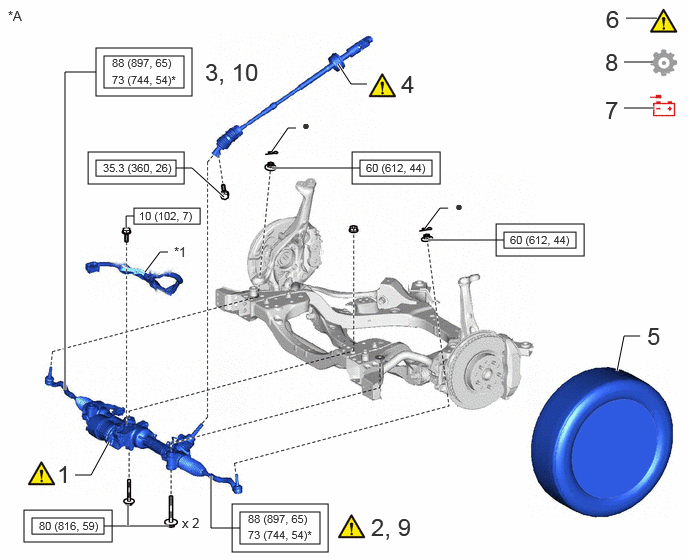
| Procedure | Part Name Code | 
|

|

|
|
|---|---|---|---|---|---|
| 1 | RACK AND PINION POWER STEERING GEAR ASSEMBLY | 44250 | ( ) |
- | - |
| 2 | CONNECT TIE ROD ASSEMBLY LH | 45470 | ()
|
- | - |
| 3 | CONNECT TIE ROD ASSEMBLY RH | 45460 | - | - | - |
| 4 | NO. 2 STEERING INTERMEDIATE SHAFT ASSEMBLY | 45260 | ()
|
- | - |
| 5 | FRONT WHEEL | - | - | - | - |
| 6 | ALIGN FRONT WHEELS FACING STRAIGHT AHEAD | - | - | - | - |
| 7 | CONNECT CABLE TO NEGATIVE AUXILIARY BATTERY TERMINAL | - | - | - | - |
| 8 | INSPECT AND ADJUST FRONT WHEEL ALIGNMENT | - | - | - | ()
|
| 9 | FULLY TIGHTEN TIE ROD ASSEMBLY LH | 45470 | ()
|
- | - |
| 10 | FULLY TIGHTEN TIE ROD ASSEMBLY RH | 45460 | - | - | - |
| *A | for LHD | - | - |
| *1 | MOTOR COMPARTMENT MAIN WIRE | - | - |

|
Tightening torque for "Major areas involving basic vehicle performance such as moving/turning/stopping": N*m (kgf*cm, ft.*lbf) | 
|
N*m (kgf*cm, ft.*lbf): Specified torque |
| * | For use with SST | ● | Non-reusable part |
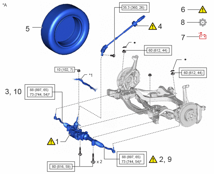
| Procedure | Part Name Code |
|
|
|
|
|---|---|---|---|---|---|
| 1 | RACK AND PINION POWER STEERING GEAR ASSEMBLY | 44250 | ()
|
- | - |
| 2 | CONNECT TIE ROD ASSEMBLY LH | 45470 | ()
|
- | - |
| 3 | CONNECT TIE ROD ASSEMBLY RH | 45460 | - | - | - |
| 4 | NO. 2 STEERING INTERMEDIATE SHAFT ASSEMBLY | 45260 | ()
|
- | - |
| 5 | FRONT WHEEL LH | - | - | - | - |
| 6 | ALIGN FRONT WHEELS FACING STRAIGHT AHEAD | - | - | - | - |
| 7 | CONNECT CABLE TO NEGATIVE AUXILIARY BATTERY TERMINAL | - | - | - | ()
|
| 8 | INSPECT AND ADJUST FRONT WHEEL ALIGNMENT | - | - | - | ()
|
| 9 | FULLY TIGHTEN TIE ROD ASSEMBLY LH | 45470 | ()
|
- | - |
| 10 | FULLY TIGHTEN TIE ROD ASSEMBLY RH | 45460 | - | - | - |
| *A | for RHD | - | - |
| *1 | MOTOR COMPARTMENT MAIN WIRE | - | - |
|
|
Tightening torque for "Major areas involving basic vehicle performance such as moving/turning/stopping": N*m (kgf*cm, ft.*lbf) |
|
N*m (kgf*cm, ft.*lbf): Specified torque |
| * | For use with SST | ● | Non-reusable part |
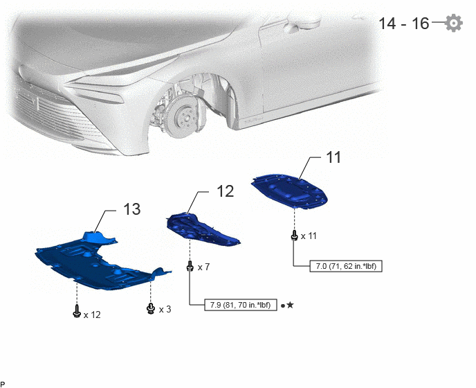
| Procedure | Part Name Code |
|
|
|
|
|---|---|---|---|---|---|
| 11 | FRONT COMPARTMEMT UNDER COVER ASSEMBLY | 51420A | - | - | - |
| 12 | FRONT LOWER SUSPENSION MEMBER PROTECTOR | 51219 | - | - | |
| 13 | FRONT COMPARTMENT UNDER COVER | 51441N | - | - | - |
| 14 | POWER STEERING ECU INITIAL SETTING (w/ Advanced Park) | - | - | - | ()
|
| 15 | INITIALIZATION AFTER RECONNECTING AUXILIARY BATTERY TERMINAL | - | - | - | ()
|
| 16 | UPDATE ECU SECURITY KEY | - | - | - | ()
|
|
|
N*m (kgf*cm, ft.*lbf): Specified torque | ● | Non-reusable part |
| ★ | Precoated part | - | - |
CAUTION / NOTICE / HINT
- HINT:
- ·
Use the same procedure for RHD and LHD vehicles.
·The procedure listed below is for LHD vehicles.
PROCEDURE

 44250
1.INSTALL RACK AND PINION POWER STEERING GEAR ASSEMBLY
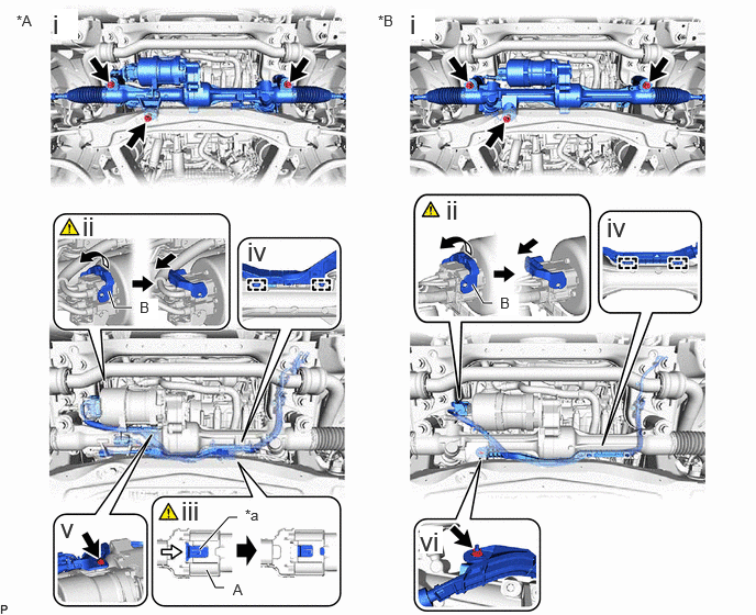
| *A | for LHD | *B | for RHD |
| *a | Green Lock | - | - |

|
Slide | - | - |
Install the rack and pinion power steering gear assembly with the 3 bolts and nut.
- Torque:
- 80 N*m (816 kgf*cm, 59 ft.*lbf)
Connect the connector (B) of the motor compartment main wire to the rack and pinion power steering gear assembly.
- HINT:
-
Connect the connector with the lock lever by first inserting the connector (B) as far as it will go, moving the lock lever as shown in the illustration and then pushing in the lock.
for LHD:
Connect the connector (A), and slide the green lock to lock it as shown in the illustration.
- NOTICE:
-
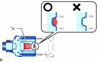 0.938,1.563 0.75,1 0.75,1 0.583,1 true 0.375,0.917 0.604,1.167 0.229,0.25 10 false *a
*a Green Lock
-
Check that the green lock is securely locked.
Attach the 2 clamps.
for LHD:
Connect the motor compartment main wire to the rack and pinion power steering gear assembly with the bolt.
- Torque:
- 10 N*m (102 kgf*cm, 7 ft.*lbf)
for RHD:
Connect the motor compartment main wire to the rack and pinion power steering gear assembly with the nut.
- Torque:
- 10 N*m (102 kgf*cm, 7 ft.*lbf)
45470
2.CONNECT TIE ROD ASSEMBLY LH
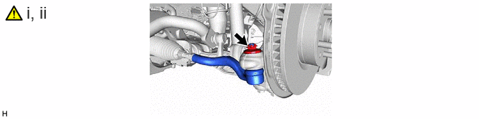
Connect the tie rod assembly LH to the front lower ball joint assembly with the nut.
- Torque:
- 60 N*m (612 kgf*cm, 44 ft.*lbf)
Install a new clip.
- NOTICE:
-
Further tighten the nut up to 60° if the holes for the clip are not aligned.
45460
3.CONNECT TIE ROD ASSEMBLY RH
Perform the same procedure as for the LH side.
45260
4.CONNECT NO. 2 STEERING INTERMEDIATE SHAFT ASSEMBLY
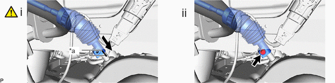
| *a | Matchmark | - | - |
Align the matchmarks on the No. 2 steering intermediate shaft assembly with the matchmarks on the rack and pinion power steering gear assembly.
Install the bolt.
- Torque:
- 35.3 N*m (360 kgf*cm, 26 ft.*lbf)
5.INSTALL FRONT WHEEL
6.ALIGN FRONT WHEELS FACING STRAIGHT AHEAD
7.CONNECT CABLE TO NEGATIVE AUXILIARY BATTERY TERMINAL
8.INSPECT AND ADJUST FRONT WHEEL ALIGNMENT
45470
9.FULLY TIGHTEN TIE ROD ASSEMBLY LH
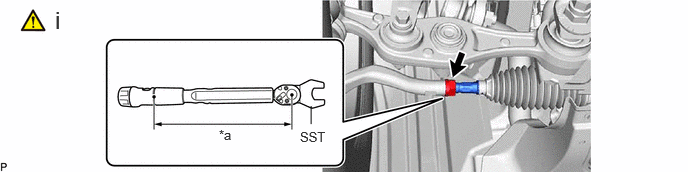
| *a | Torque Wrench Fulcrum Length | - | - |
Connect the tie rod assembly LH to the front lower ball joint assembly with the nut.
- SST
- 09612-24014 (09617-24011)
- Torque:
- Specified tightening torque : 88 N*m (897 kgf*cm, 65 ft.*lbf)
- HINT:
- ·
Calculate the torque wrench reading when changing the fulcrum length of the torque wrench.
Click hereGeneral>INTRODUCTION>REPAIR INSTRUCTION>PRECAUTION
·When using SST (fulcrum length of 52 mm (2.047 in.)) + torque wrench (fulcrum length of 255 mm (10.039 in.)): 73 N*m (744 kgf*cm, 54 ft.*lbf)
45460
10.FULLY TIGHTEN TIE ROD ASSEMBLY RH
Perform the same procedure as for the LH side.
51420A
11.INSTALL FRONT COMPARTMEMT UNDER COVER ASSEMBLY
51219
12.INSTALL FRONT LOWER SUSPENSION MEMBER PROTECTOR
51441N
13.INSTALL FRONT COMPARTMENT UNDER COVER
14. POWER STEERING ECU INITIAL SETTING
15. INITIALIZATION AFTER RECONNECTING AUXILIARY BATTERY TERMINAL
Click hereGeneral>SETUP>WHEN DISCONNECTING OR RECONNECTING BATTERY TERMINAL>WORK PROCEDURE
- HINT:
-
When disconnecting and reconnecting the battery, there is an automatic learning function that completes learning when the respective system is used.
-
Click hereGeneral>SETUP>WHEN DISCONNECTING OR RECONNECTING BATTERY TERMINAL>AUTOMATIC LEARNING CHART
16. UPDATE ECU SECURITY KEY