BRAKE SYSTEM (OTHER) BRAKE PEDAL(for RHD) REMOVAL
CAUTION / NOTICE / HINT
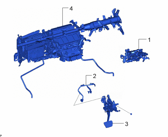
| Procedure | Part Name Code | 
|

|

|
|
|---|---|---|---|---|---|
| 1 | STEERING COLUMN ASSEMBLY | 45250 | - | - | - |
| 2 | FRONT COMPARTMENT MAIN WIRE | 82111C | - | - | - |
| 3 | DISCONNECT BRAKE PEDAL SUPPORT ASSEMBLY | 47110 | - | - | - |
| 4 | INSTRUMENT PANEL REINFORCEMENT ASSEMBLY WITH AIR CONDITIONING UNIT ASSEMBLY | - | - | - | - |
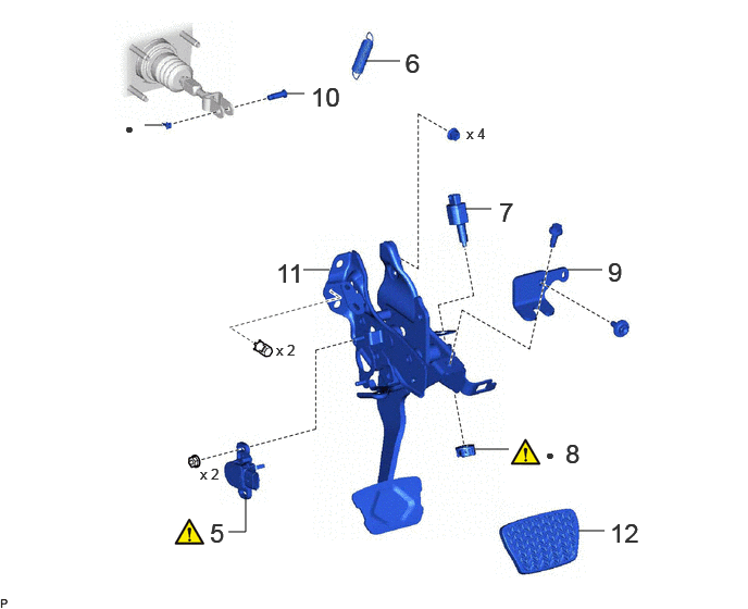
| Procedure | Part Name Code |
|
|
|
|
|---|---|---|---|---|---|
| 5 | BRAKE PEDAL STROKE SENSOR ASSEMBLY | 89510D | ( ) |
- | - |
| 6 | BRAKE PEDAL RETURN SPRING | 47101A | - | - | - |
| 7 | STOP LIGHT SWITCH ASSEMBLY | 84340 | - | - | - |
| 8 | STOP LIGHT SWITCH MOUNTING ADJUSTER | 84345 | ()
|
- | - |
| 9 | BRAKE PEDAL SUPPORT REINFORCEMENT | 55179 | - | - | - |
| 10 | PUSH ROD PIN | 47264A | - | - | - |
| 11 | REMOVE BRAKE PEDAL SUPPORT ASSEMBLY | 47110 | - | - | - |
| 12 | BRAKE PEDAL PAD | 47121 | - | - | - |
| ● | Non-reusable part | - | - |
CAUTION / NOTICE / HINT
The necessary procedures (adjustment, calibration, initialization, or registration) that must be performed after parts are removed, installed, or replaced during brake pedal support assembly removal/installation are shown below.
| Replaced Part or Performed Procedure | Necessary Procedure | Effect/Inoperative Function when Necessary Procedure not Performed | Link |
|---|---|---|---|
|
*: Even when not replacing the part, it is necessary to perform the specified necessary procedures after installation. |
|||
| Disconnect cable from negative (-) auxiliary battery terminal | Memorize steering angle neutral point | Parking assist monitor system | ()
|
| Panoramic view monitor system | ()
|
||
·
Brake pedal stroke sensor assembly* ·
Brake pedal* |
Perform "Calibration" | ·
DTCs are stored ·
ABS warning light illuminates ·
Brake system warning light (yellow indicator) illuminates ·
Slip indicator light illuminates ·
Electronically controlled brake system disabled or malfunctions |
()
|
| Brake pedal stroke sensor assembly adjustment | Electronically controlled brake system malfunctions | ||
| Steering sensor (Including removal and installation) | Steering angle neutral point | Parking assist monitor system | ()
|
| Panoramic view monitor system | ()
|
||
- HINT:
-
When the cable is disconnected/reconnected to the auxiliary battery terminal, systems temporarily stop operating. However, each system has a function that completes learning the first time the system is used.
- ·
Learning completes when vehicle is driven
Effect/Inoperative Function When Necessary Procedures are not Performed Necessary Procedures Link Lane tracing assist system Drive the vehicle straight ahead at 35 km/h (22 mph) or more for 5 seconds or more. ( )
Pre-collision system Adaptive high beam system
·Learning completes when vehicle is operated normally
Effect/Inoperative Function When Necessary Procedures are not Performed Necessary Procedures Link Air conditioning system After the ignition switch is turned to ON, theservo motor and expansion valve standardposition is recognized. -
PROCEDURE

 45250
1.REMOVE STEERING COLUMN ASSEMBLY
for Manual Tilt and Manual Telescopic Steering Column:
for Power Tilt and Power Telescopic Steering Column:
82111C
2.DISCONNECT FRONT COMPARTMENT MAIN WIRE

47110
3.DISCONNECT BRAKE PEDAL SUPPORT ASSEMBLY

4.REMOVE INSTRUMENT PANEL REINFORCEMENT ASSEMBLY WITH AIR CONDITIONING UNIT ASSEMBLY
89510D
5.REMOVE BRAKE PEDAL STROKE SENSOR ASSEMBLY
|
|
Click here()
|
47101A
6.REMOVE BRAKE PEDAL RETURN SPRING

84340
7.REMOVE STOP LIGHT SWITCH ASSEMBLY
84345
8.REMOVE STOP LIGHT SWITCH MOUNTING ADJUSTER
|
|
Click here()
|
55179
9.REMOVE BRAKE PEDAL SUPPORT REINFORCEMENT

47264A
10.REMOVE PUSH ROD PIN
Remove the clip and push rod pin.

47110
11.REMOVE BRAKE PEDAL SUPPORT ASSEMBLY

47121
12.REMOVE BRAKE PEDAL PAD