HYBRID / BATTERY CONTROL HV BATTERY INSTALLATION
CAUTION / NOTICE / HINT
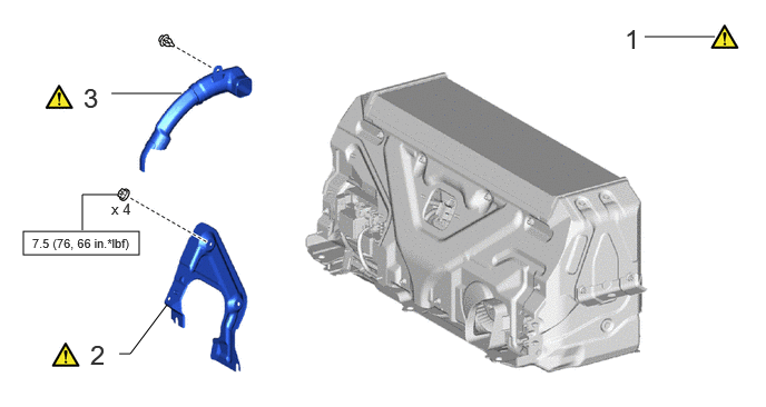
| Procedure | Part Name Code | 
|

|

|
|
|---|---|---|---|---|---|
| 1 | INSPECT NO. 2 EV BATTERY INTAKE FILTER | G92DJB | ( ) |
- | - |
| 2 | NO. 9 EV BATTERY SHIELD PANEL | G92QBA | ()
|
- | - |
| 3 | EV BATTERY DUCT SUB-ASSEMBLY | G9209C | ()
|
- | - |

|
N*m (kgf*cm, ft.*lbf): Specified torque | - | - |
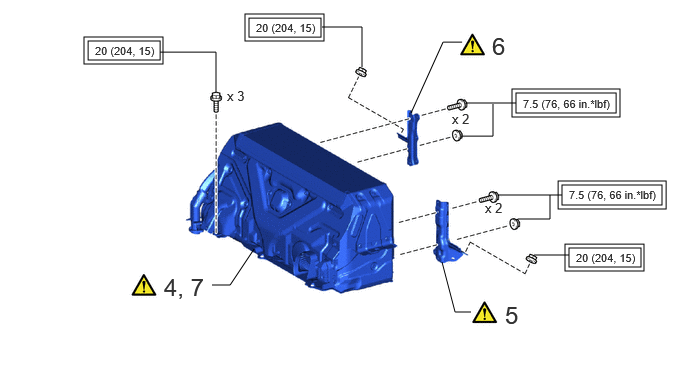
| Procedure | Part Name Code |
|
|
|
|
|---|---|---|---|---|---|
| 4 | TEMPORARILY TIGHTEN EV SUPPLY BATTERY ASSEMBLY | G9510B | ()
|
- | - |
| 5 | EV BATTERY BRACKET LH | G928BA | ()
|
- | - |
| 6 | EV BATTERY BRACKET RH | G928AA | ()
|
- | - |
| 7 | TIGHTEN EV SUPPLY BATTERY ASSEMBLY | G9510B | ()
|
- | - |

|
Tightening torque for "Major areas involving basic vehicle performance such as moving/turning/stopping": N*m (kgf*cm, ft.*lbf) | - | - |
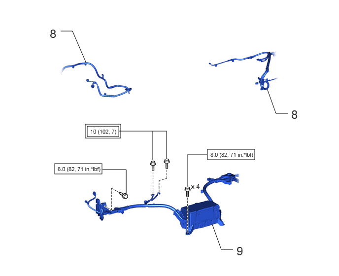
| Procedure | Part Name Code |
|
|
|
|
|---|---|---|---|---|---|
| 8 | FLOOR WIRE | 82161 | - | - | - |
| 9 | NO. 1 LUGGAGE ROOM WIRE | 82181 | - | - | - |
|
|
Tightening torque for "Major areas involving basic vehicle performance such as moving/turning/stopping": N*m (kgf*cm, ft.*lbf) |
|
N*m (kgf*cm, ft.*lbf): Specified torque |
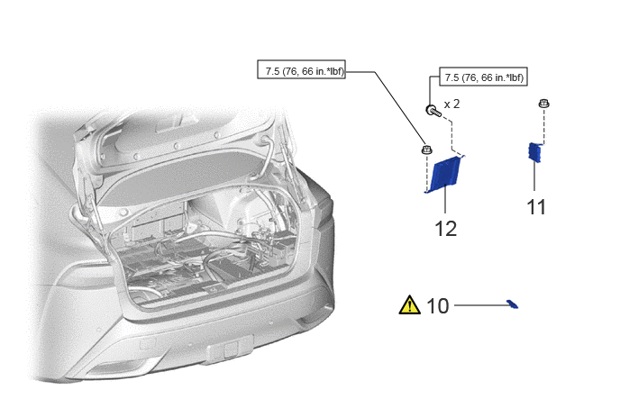
| Procedure | Part Name Code |
|
|
|
|
|---|---|---|---|---|---|
| 10 | NO. 3 INDOOR ELECTRICAL KEY ANTENNA ASSEMBLY | 899A0B | ()
|
- | - |
| 11 | CLEARANCE WARNING ECU ASSEMBLY | 89340A | - | - | - |
| 12 | STEREO COMPONENT AMPLIFIER ASSEMBLY WITH BRACKET | - | - | - | - |
|
|
N*m (kgf*cm, ft.*lbf): Specified torque | - | - |
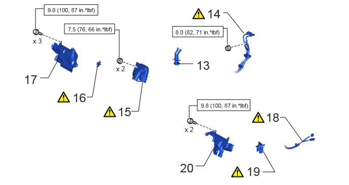
| Procedure | Part Name Code |
|
|
|
|
|---|---|---|---|---|---|
| 13 | NO. 4 EV BATTERY EXHAUST DUCT | G92F4A | - | - | - |
| 14 | FLOOR UNDER WIRE | 821H1 | ()
|
- | - |
| 15 | NO. 10 EV BATTERY SHIELD PANEL | G92QCA | ()
|
- | - |
| 16 | BATTERY COVER LOCK STRIKER | G9295B | ()
|
- | - |
| 17 | CENTER NO. 1 FLOOR TO BLACE EXTENSION | 64227A | - | - | - |
| 18 | FLOOR WIRE | 82161 | ()
|
- | - |
| 19 | NO. 2 EV BATTERY CLAMP COVER | G92P6A | ()
|
- | - |
| 20 | CENTER NO. 2 FLOOR TO BRACE EXTENSION | 64228A | - | - | - |
|
|
N*m (kgf*cm, ft.*lbf): Specified torque | - | - |
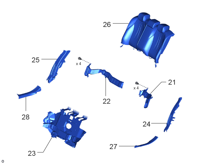
| Procedure | Part Name Code |
|
|
|
|
|---|---|---|---|---|---|
| 21 | NO. 4 EV BATTERY INTAKE DUCT | G92D4A | - | - | - |
| 22 | NO. 2 EV BATTERY INTAKE DUCT | G92D2A | - | - | - |
| 23 | NO. 1 ROOM PARTITION PAD | 64273D | - | - | - |
| 24 | REAR SEAT SIDE GARNISH LH | 62552F | - | - | - |
| 25 | REAR SEAT SIDE GARNISH RH | 62551F | - | - | - |
| 26 | BENCH TYPE REAR SEATBACK ASSEMBLY | - | - | - | - |
| 27 | REAR DOOR SCUFF PLATE INSIDE LH | 67918F | - | - | - |
| 28 | REAR DOOR SCUFF PLATE INSIDE RH | 67917F | - | - | - |
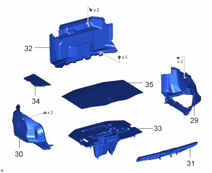
| Procedure | Part Name Code |
|
|
|
|
|---|---|---|---|---|---|
| 29 | LUGGAGE COMPARTMENT TRIM COVER INNER RH | 64721 | - | - | - |
| 30 | LUGGAGE COMPARTMENT TRIM COVER INNER LH | 64722 | - | - | - |
| 31 | REAR FLOOR FINISH PLATE | 58387 | - | - | - |
| 32 | FRONT LUGGAGE COMPARTMENT TRIM COVER | 64075B | - | - | - |
| 33 | TOOL BOX | 75201A | - | - | - |
| 34 | LUGGAGE COMPARTMENT TRIM COVER LH | 64715D | - | - | - |
| 35 | LUGGAGE COMPARTMENT MAT SUB-ASSEMBLY | 64701 | - | - | - |
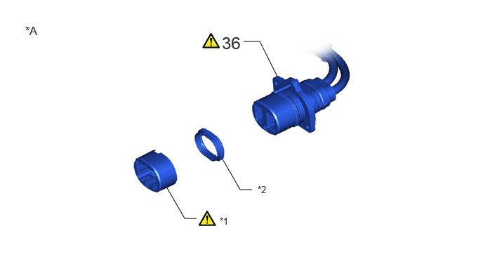
| Procedure | Part Name Code |
|
|
|
|
|---|---|---|---|---|---|
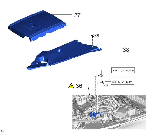
| 36 | FC CONVERTER POWER OUTLET CABLE (INVERTER WITH CONVERTER ASSEMBLY) | G9200A | ()
|
- | - |
| *A | If the front holder and gasket are left in the stack, remove them using the following procedure | - | - |
| *1 | FRONT HOLDER | *2 | GASKET |
| Procedure | Part Name Code |
|
|
|
|
|---|---|---|---|---|---|
| 36 | FC CONVERTER POWER OUTLET CABLE (INVERTER WITH CONVERTER ASSEMBLY) | G9200A | ()
|
- | - |
| 37 | FC STACK COVER SUB-ASSEMBLY | 1A906 | - | - | - |
| 38 | UPPER RADIATOR SUPPORT SEAL | 53292A | - | - | - |
|
|
Tightening torque for "Major areas involving basic vehicle performance such as moving/turning/stopping": N*m (kgf*cm, ft.*lbf) |
|
N*m (kgf*cm, ft.*lbf): Specified torque |
| Procedure | Part Name Code |
|
|
|
|
|---|---|---|---|---|---|
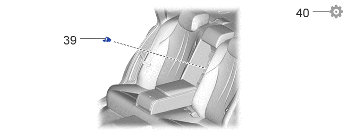
| 39 | SERVICE PLUG GRIP | G3834 | - | - | - |
| 40 | PERFORM UTILITY | - | - | - | ()
|
PROCEDURE

 G92DJB
1.INSPECT NO. 2 EV BATTERY INTAKE FILTER
G92QBA
2.INSTALL NO. 9 EV BATTERY SHIELD PANEL
|
|
|
- Torque:
- 7.5 N*m (76 kgf*cm, 66 in.*lbf)
G9209C
3.INSTALL EV BATTERY DUCT SUB-ASSEMBLY
|
|
|
G9510B
4.TEMPORARILY TIGHTEN EV SUPPLY BATTERY ASSEMBLY
|
|
|
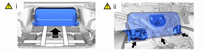
Place wooden blocks as shown in the illustration and install the EV supply battery assembly by sliding it on the wooden blocks.
- NOTICE:
- ·
To prevent the wire harness from being caught, make sure to bundle the wire harness using insulating tape or equivalent.
·Use cardboard or another similar material to protect the EV supply battery assembly and vehicle body from damage.
·Since the EV supply battery assembly is very heavy, 2 people are needed to remove it. When removing the HV battery, be careful not to damage the parts around it.
·When removing/installing/moving the EV supply battery assembly, make sure not to tilt it more than 80°.
·If the EV supply battery assembly has been struck or dropped, replace it.
Temporarily install the EV supply battery assembly to the vehicle body with the 3 bolts.
- NOTICE:
-
Do not allow foreign matter, such as grease or oil, to adhere to the bolts of the EV supply battery assembly.
G928BA
5.INSTALL EV BATTERY BRACKET LH
|
|
|
- Torque:
- EV battery side : 7.5 N*m (76 kgf*cm, 66 in.*lbf)
- Vehicle body side : 20 N*m (204 kgf*cm, 15 ft.*lbf)
G928AA
6.INSTALL EV BATTERY BRACKET RH
|
|
|
- Torque:
- EV battery side : 7.5 N*m (76 kgf*cm, 66 in.*lbf)
- Vehicle body side : 20 N*m (204 kgf*cm, 15 ft.*lbf)
G9510B
7.TIGHTEN EV SUPPLY BATTERY ASSEMBLY
|
|
|

Tighten the 3 bolts.
- Torque:
- 20 N*m (204 kgf*cm, 15 ft.*lbf)
82161
8.INSTALL FLOOR WIRE
82181
9.INSTALL NO. 1 LUGGAGE ROOM WIRE
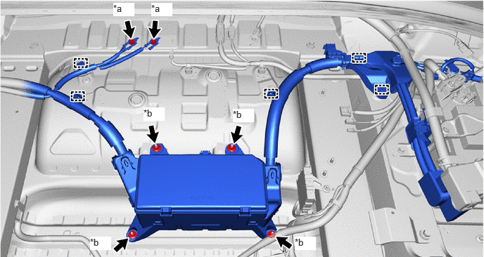
| *a | Bolt | *b | Nut |
- Torque:
- Bolt : 10 N*m (102 kgf*cm, 7 ft.*lbf)
- Nut : 8.0 N*m (82 kgf*cm, 71 in.*lbf)
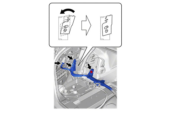
- Torque:
- 8.0 N*m (82 kgf*cm, 71 in.*lbf)
899A0B
10.INSTALL NO. 3 INDOOR ELECTRICAL KEY ANTENNA ASSEMBLY
|
|
Click here()
|
89340A
11.INSTALL CLEARANCE WARNING ECU ASSEMBLY
12.INSTALL STEREO COMPONENT AMPLIFIER ASSEMBLY WITH BRACKET
G92F4A
13.INSTALL NO. 4 EV BATTERY EXHAUST DUCT
821H1
14.CONNECT FLOOR UNDER WIRE
|
|
|
- Torque:
- 8.0 N*m (82 kgf*cm, 71 in.*lbf)
G92QCA
15.INSTALL NO. 10 EV BATTERY SHIELD PANEL
|
|
|
- Torque:
- 7.5 N*m (76 kgf*cm, 66 in.*lbf)
G9295B
16.INSTALL BATTERY COVER LOCK STRIKER
|
|
|

| *1 | Battery Cover Lock Striker | - | - |
| *a | Button | *b | Push |
Install the battery cover lock striker, then push the button to lock it.
64227A
17.INSTALL CENTER NO. 1 FLOOR TO BLACE EXTENSION
- Torque:
- 9.8 N*m (100 kgf*cm, 87 in.*lbf)
82161
18.CONNECT FLOOR WIRE
|
|
|
G92P6A
19.INSTALL NO. 2 EV BATTERY CLAMP COVER
|
|
|
64228A
20.INSTALL CENTER NO. 2 FLOOR TO BRACE EXTENSION
- Torque:
- 9.8 N*m (100 kgf*cm, 87 in.*lbf)
G92D4A
21.INSTALL NO. 4 EV BATTERY INTAKE DUCT
G92D2A
22.INSTALL NO. 2 EV BATTERY INTAKE DUCT
64273D
23.INSTALL NO. 1 ROOM PARTITION PAD
62552F
24.INSTALL REAR SEAT SIDE GARNISH LH
62551F
25.INSTALL REAR SEAT SIDE GARNISH RH
26.INSTALL BENCH TYPE REAR SEATBACK ASSEMBLY
67918F
27.INSTALL REAR DOOR SCUFF PLATE INSIDE LH
67917F
28.INSTALL REAR DOOR SCUFF PLATE INSIDE RH
64721
29.INSTALL LUGGAGE COMPARTMENT TRIM COVER INNER RH
64722
30.INSTALL LUGGAGE COMPARTMENT TRIM COVER INNER LH
58387
31.INSTALL REAR FLOOR FINISH PLATE
64075B
32.INSTALL FRONT LUGGAGE COMPARTMENT TRIM COVER
75201A
33.INSTALL TOOL BOX
64715D
34.INSTALL LUGGAGE COMPARTMENT TRIM COVER LH
64701
35.INSTALL LUGGAGE COMPARTMENT MAT SUB-ASSEMBLY
G9200A
36.CONNECT FC CONVERTER POWER OUTLET CABLE (INVERTER WITH CONVERTER ASSEMBLY)
|
|
|
If the front holder and gasket are removed, install them using the following procedure.
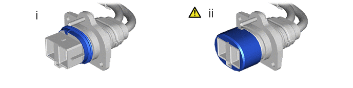
Install the gasket to the housing.
- HINT:
-
Install by aligning the protrusion of the gasket with the housing groove.
Install the front holder to the housing.
- NOTICE:
-
Push in the front holder until a "click" sound is heard. After pushing it in, check that it is not removed.
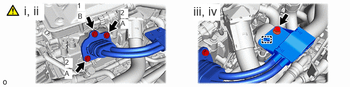
Connect the FC converter power outlet cable (inverter with converter assembly) to the FC converter.
Tighten the 2 bolts (A) and bolt (B) in the order shown in the illustration.
- Torque:
- 8.0 N*m (82 kgf*cm, 71 in.*lbf)
- NOTICE:
-
Installing the bolts in an incorrect order may damage the FC converter and FC converter power outlet cable (inverter with converter assembly).
Engage the clamp.
Install the bolt.
- Torque:
- 8.0 N*m (82 kgf*cm, 71 in.*lbf)
1A906
37.INSTALL FC STACK COVER SUB-ASSEMBLY
53292A
38.INSTALL UPPER RADIATOR SUPPORT SEAL
G3834
39.INSTALL SERVICE PLUG GRIP
40. PERFORM UTILITY
|
|
|