ADVANCED DRIVER ASSISTANCE SYSTEM FRONT CAMERA SYSTEM C1A7587 Steering Vibrator System Missing Message
DESCRIPTION
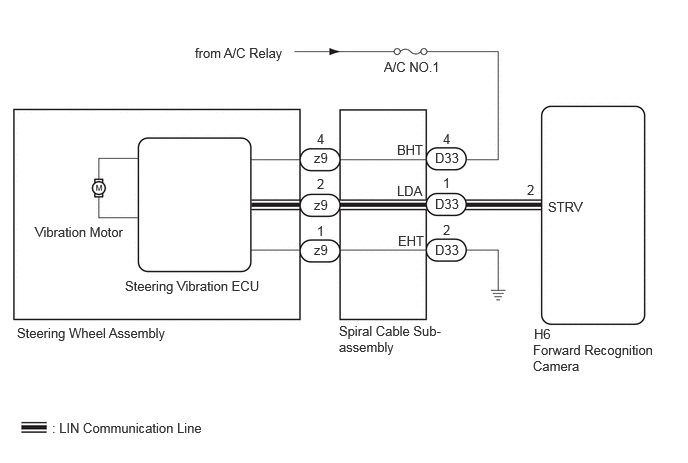
The forward recognition camera communicates with the steering vibration ECU (steering wheel assembly) via LIN communication.
If a communication error between the forward recognition camera and steering vibration ECU (steering wheel assembly) is detected, DTC C1A7587 is stored.
| DTC No. | Detection Item | DTC Detection Condition | Trouble Area | DTC Output from | Priority |
|---|---|---|---|---|---|
| C1A7587 | Steering Vibrator System Missing Message | While the vehicle is being driven at 5 km/h (4 mph) or more and the lane control system is on, a LIN communication error is detected between the steering vibration ECU (steering wheel assembly) and forward recognition camera for 5 minutes or more. | ·
Forward recognition camera ·
Steering vibration ECU (steering wheel assembly) ·
Wire harness or connector ·
Spiral cable sub-assembly |
Front Recognition Camera | A |
WIRING DIAGRAM
CAUTION / NOTICE / HINT
- NOTICE:
- ·
The vehicle is equipped with a Supplemental Restraint System (SRS) which includes components such as airbags. Before servicing (including removal or installation of parts), be sure to read the precaution for Supplemental Restraint System.
Click hereVehicle Interior>SUPPLEMENTAL RESTRAINT SYSTEMS>AIRBAG SYSTEM>PRECAUTION
·When replacing the forward recognition camera, always replace it with a new one. If a forward recognition camera which was installed to another vehicle is used, the information stored in the forward recognition camera will not match the information from the vehicle. As a result, a DTC may be stored.
·When the forward recognition camera is replaced with a new one, make sure to read Before Starting Adjustment, then perform optical axis alignment for the forward recognition camera and clear the vehicle control history for each system.
- HINT:
-
Forward recognition camera axis alignment can be performed by using either One Time Recognition, Sequential Recognition or Driving Adjustment.
-
One Time Recognition: Click hereADAS / AD>ADVANCED DRIVER ASSISTANCE SYSTEM>FRONT CAMERA>TARGET ADJUSTMENT(ONE TIME RECOGNITION)
-
Sequential Recognition: Click hereADAS / AD>ADVANCED DRIVER ASSISTANCE SYSTEM>FRONT CAMERA>TARGET ADJUSTMENT(SEQUENTIAL RECOGNITION)
-
Driving Adjustment: Click hereADAS / AD>ADVANCED DRIVER ASSISTANCE SYSTEM>FRONT CAMERA>DRIVING ADJUSTMENT
PROCEDURE
- Result:
Proceed to OK NG
OK
NG
Turn the ignition switch to ON.
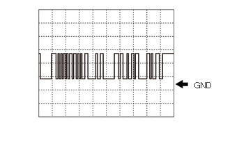
Using an oscilloscope, measure the waveform at the D33 spiral cable sub-assembly connector.
- Measurement Condition:
Tester Connection Switch Condition Tester Range Click Location & Routing(D33)Location & Routingewd_type=routing;type=c;code=D33
Click Connector(D33)Instrument Panel>Instrument Panel Wire>Spiral Cable Sub-Assemblyewd_type=component;type=c;code=D33;pinno=1
D33-1 (LDA) - Body ground Ignition switch ON 5 V/DIV., 1 ms/DIV.
- NOTICE:
-
The oscilloscope waveform is for reference only and does not include noise, fluctuations, etc.
- OK:
A waveform similar to that in the illustration can be observed.
- Result:
Proceed to OK NG
OK
NG
Measure the voltage according to the value(s) in the table below.
- Standard Voltage:
Tester Connection Switch Condition Specified Condition Click Location & Routing(D33)Location & Routingewd_type=routing;type=c;code=D33
Click Connector(D33)Instrument Panel>Instrument Panel Wire>Spiral Cable Sub-Assemblyewd_type=component;type=c;code=D33;pinno=4
D33-4 (BHT) - Body ground Ignition switch ON 11 to 14 V
- Result:
Proceed to OK NG
OK
NG
Measure the resistance according to the value(s) in the table below.
- Standard Resistance:
Tester Connection Condition Specified Condition Click Location & Routing(D33)Location & Routingewd_type=routing;type=c;code=D33
Click Connector(D33)Instrument Panel>Instrument Panel Wire>Spiral Cable Sub-Assemblyewd_type=component;type=c;code=D33;pinno=2
D33-2 (EHT) - Body ground Always Below 1 Ω
- Result:
Proceed to OK NG
OK
NG
Pre-procedure1
Disconnect the H6 forward recognition camera connector.
Procedure1
Measure the resistance according to the value(s) in the table below.
- Standard Resistance:
Tester Connection Condition Specified Condition Click Location & Routing(D33,H6)Location & Routingewd_type=routing;type=c,c;code=D33,H6
Click Connector(D33)Instrument Panel>Instrument Panel Wire>Spiral Cable Sub-Assemblyewd_type=component;type=c;code=D33;pinno=1
Click Connector(H6)Body>No. 1 Roof Wire>Forward Recognition Cameraewd_type=component;type=c;code=H6;pinno=2
D33-1 (LDA) - H6-2 (STRV) Always Below 1 Ω D33-1 (LDA) or H6-2 (STRV) - Body ground Always 10 kΩ or higher
- Result:
Proceed to OK NG
Post-procedure1
None
OK
NG