DRIVE SHAFT / PROPELLER SHAFT REAR DRIVE SHAFT ASSEMBLY INSTALLATION
CAUTION / NOTICE / HINT
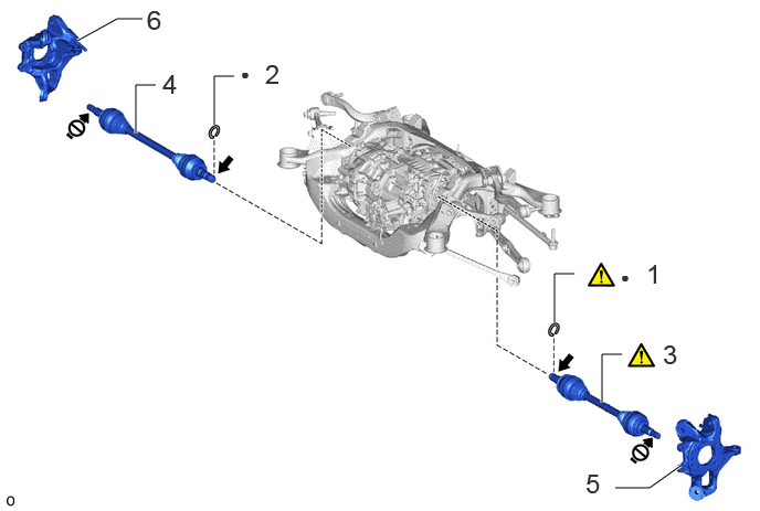
| Procedure | Part Name Code | 
|

|

|
|
|---|---|---|---|---|---|
| 1 | DRIVE SHAFT SNAP RING LH | 43425B | ( ) |
- | - |
| 2 | DRIVE SHAFT SNAP RING RH | 43425A | - | - | - |
| 3 | REAR DRIVE SHAFT ASSEMBLY LH | 42340B | ()
|
- | - |
| 4 | REAR DRIVE SHAFT ASSEMBLY RH | 42330 | - | - | - |
| 5 | REAR AXLE ASSEMBLY LH | - | - | - | - |
| 6 | REAR AXLE ASSEMBLY RH | - | - | - | - |
| ● | Non-reusable part | - | - |

|
Toyota Genuine ATF WS | 
|
Do not apply lubricants to the threaded parts |
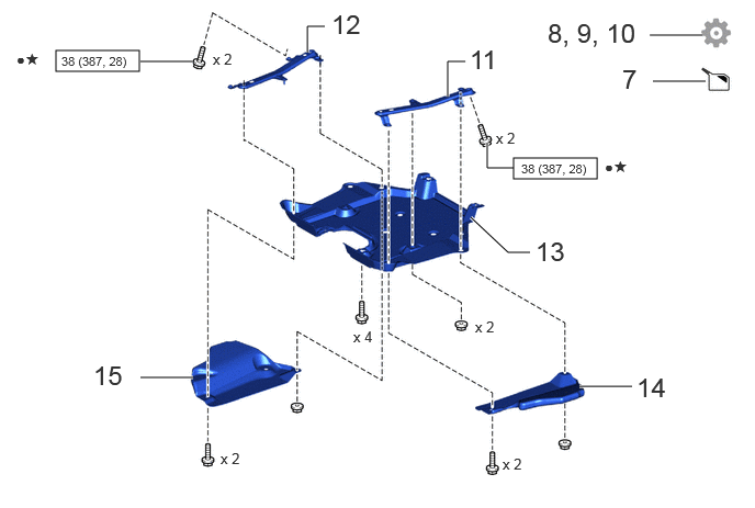
| Procedure | Part Name Code |
|
|
|
|
|---|---|---|---|---|---|
| 7 | ADD HYBRID TRANSAXLE FLUID | - | - | ()
|
- |
| 8 | BLEED AIR FROM HYBRID TRANSAXLE FLUID LINE | - | - | - | ()
|
| 9 | INSPECT HYBRID TRANSAXLE FLUID | - | - | - | ()
|
| 10 | INSPECT INSPECT FOR HYBRID TRANSAXLE FLUID LEAK | - | - | - | ()
|
| 11 | REAR SUSPENSION MEMBER BRACE LH | 52296 | - | - | - |
| 12 | REAR SUSPENSION MEMBER BRACE RH | 52295 | - | - | - |
| 13 | REAR SUSPENSION BRACE COVER | 53661B | - | - | - |
| 14 | NO. 1 DIFFERENTIAL SUPPORT PROTECTOR | 52383E | - | - | - |
| 15 | NO. 2 DIFFERENTIAL SUPPORT PROTECTOR | 52384C | - | - | - |

|
N*m (kgf*cm, ft.*lbf): Specified torque | ● | Non-reusable part |
| ★ | Precoated part | - | - |
PROCEDURE

 43425B
1.INSTALL DRIVE SHAFT SNAP RING LH
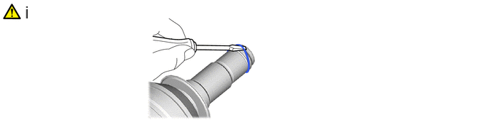
Install a new shaft snap ring.
- NOTICE:
- ·
Do not damage the spline of the rear drive inboard joint assembly LH.
·The shaft snap ring should be installed completely.
43425A
2.INSTALL DRIVE SHAFT SNAP RING RH
Use the same procedure as for the LH side.
42340B
3.INSTALL REAR DRIVE SHAFT ASSEMBLY LH
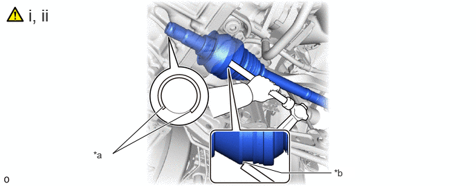
| *a | Opening Facing | *b | Press-fit wall |
Coat the spline of the rear drive inboard joint assembly with Toyota Genuine ATF WS.
Align the inboard joint splines, and using a brass bar and a hammer, install the rear drive shaft assembly LH.
- NOTICE:
- ·
Set the shaft snap ring in the groove with the opening facing downwards and centered radially.
·Do not damage the oil seal, boot and dust cover.
·Make sure to follow the proper handling and installation procedures. If the rear drive shaft assembly LH is installed at too large an angle or slides too much, it may fall out of the groove of the joint.
·Do not tap the end of the rear drive shaft assembly LH with a hammer, etc.
- HINT:
- ·
Determine whether the rear drive shaft assembly LH is completely tapped in by checking for changes in the tapping sound or the reaction of the brass bar.
·Use the press-fit wall of the rear drive shaft inboard joint LH when tapping.
42330
4.INSTALL REAR DRIVE SHAFT ASSEMBLY RH
Use the same procedure as for the LH side.
5.INSTALL REAR AXLE ASSEMBLY LH
6.INSTALL REAR AXLE ASSEMBLY RH
Use the same procedure as for the LH side.
7.ADD HYBRID TRANSAXLE FLUID
|
|
Click here()
|
8.BLEED AIR FROM HYBRID TRANSAXLE FLUID LINE
|
|
Click here()
|
9.INSPECT HYBRID TRANSAXLE FLUID
|
|
Click here()
|
10.INSPECT INSPECT FOR HYBRID TRANSAXLE FLUID LEAK
|
|
Click here()
|
52296
11.INSTALL REAR SUSPENSION MEMBER BRACE LH
- Torque:
- 38 N*m (387 kgf*cm, 28 ft.*lbf)
52295
12.INSTALL REAR SUSPENSION MEMBER BRACE RH
Use the same procedure as for the LH side.
53661B
13.INSTALL REAR SUSPENSION BRACE COVER
52383E
14.INSTALL NO. 1 DIFFERENTIAL SUPPORT PROTECTOR
52384C
15.INSTALL NO. 2 DIFFERENTIAL SUPPORT PROTECTOR