PARKING BRAKE ELECTRIC PARKING BRAKE SYSTEM C060962 Electric Parking Brake Switch Signal Compare Failure
DESCRIPTION
When the electric parking brake switch assembly is pulled, a lock request signal is sent from the No. 2 skid control ECU (brake actuator assembly) to the parking brake actuator assembly with bracket. When the electric parking brake switch assembly is pushed, a release request signal is sent from the No. 2 skid control ECU (brake actuator assembly) to the parking brake actuator assembly with bracket.
| DTC No. | Detection Item | DTC Detection Condition | Trouble Area | Memory | DTC Output from | Priority | Note |
|---|---|---|---|---|---|---|---|
| C060962 | Electric Parking Brake Switch Signal Compare Failure | Detection Condition 1:
·
Diagnosis Condition: - ·
Malfunction Status: Parking brake switch open or short circuit is detected ·
Detection Time: 1 second or more Detection Condition 2: ·
Diagnosis Condition: - ·
Malfunction Status: Parking brake switch stuck malfunction ·
Detection Time: - |
·
Electric parking brake switch assembly ·
Wire harness or connector ·
No. 2 skid control ECU (brake actuator assembly) |
DTC stored | Brake/EPB | A | An electric parking brake system malfunction is displayed on the multi-information display. |
| Vehicle Condition | ||||
|---|---|---|---|---|
| Pattern 1 | Pattern 2 | Pattern 3 | ||
| Diagnosis Condition | - | - | - | - |
| Malfunction Status | Parking brake switch open circuit is detected | ○ | - | - |
| Parking brake switch short circuit is detected | - | ○ | - | |
| Parking brake switch stuck malfunction | - | - | ○ | |
| Detection Time | 1 second or more | 1 second or more | - | |
| Number of Trips | 1 trip | 1 trip | 1 trip | |
- HINT:
-
DTC will be output when conditions for either of the patterns in the table above are met.
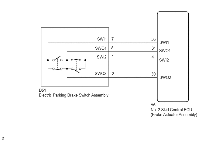
WIRING DIAGRAM
CAUTION / NOTICE / HINT
- NOTICE:
- ·
When the electric parking brake switch assembly is pulled and held for 1 second or more without being pulled fully to the lock side, both of the 2 linked contacts may turn OFF causing this DTC to be stored (this is not a system malfunction).
·To ensure that the electric parking brake does not operate, wait for 3 minutes or more with the ignition switch off, the driver door closed, and the brake pedal not depressed, then disconnect each connector, fuse and relay.
·After replacing the No. 2 skid control ECU (brake actuator assembly), perform "Calibration".
Click hereBrake>BRAKE CONTROL / DYNAMIC CONTROL SYSTEMS>ELECTRONICALLY CONTROLLED BRAKE SYSTEM>UTILITY
·After replacing the No. 2 skid control ECU (brake actuator assembly), perform "EPB Initialize" and "Acquire Tension Sensor Zero Point".
Click hereBrake>PARKING BRAKE>ELECTRIC PARKING BRAKE SYSTEM>UTILITY
PROCEDURE
OK
NG
Pre-procedure1
Turn the ignition switch off.
Disconnect the D51 electric parking brake switch assembly connector.
Disconnect the A6 No. 2 skid control ECU (brake actuator assembly) connector.
Procedure1
Measure the resistance according to the value(s) in the table below.
- Standard Resistance:
Tester Connection Condition Specified Condition Click Location & Routing(A6,D51)Location & Routingewd_type=routing;type=c,c;code=A6,D51
Click Connector(D51)Instrument Panel>Instrument Panel Wire>Electric Parking Brake Switch Assemblyewd_type=component;type=c;code=D51;pinno=7,8,1,2
A6-36 (SWI1) - D51-7 (SWI1) Always Below 1 Ω A6-31 (SWO1) - D51-8 (SWO1) Always Below 1 Ω A6-41 (SWI2) - D51-1 (SWI2) Always Below 1 Ω A6-39 (SWO2) - D51-2 (SWO2) Always Below 1 Ω A6-36 (SWI1) or D51-7 (SWI1) - Body ground Always 10 kΩ or higher A6-31 (SWO1) or D51-8 (SWO1) - Body ground Always 10 kΩ or higher A6-41 (SWI2) or D51-1 (SWI2) - Body ground Always 10 kΩ or higher A6-39 (SWO2) or D51-2 (SWO2) - Body ground Always 10 kΩ or higher
- Result:
Proceed to OK NG
Post-procedure1
None
OK
NG
Clear the DTCs.
- Chassis > Brake/EPB > Clear DTCs
- 50002 435
- Result:
Proceed to NEXT
NEXT
Check for DTCs.
- Chassis > Brake/EPB > Trouble Codes
- 50001 435
- Result:
Result Proceed to DTCs are output A DTCs are not output B
A
for LHD: Click hereBrake>BRAKE CONTROL / DYNAMIC CONTROL SYSTEMS>BRAKE ACTUATOR (for LHD)>REMOVAL
for RHD: Click hereBrake>BRAKE CONTROL / DYNAMIC CONTROL SYSTEMS>BRAKE ACTUATOR (for RHD)>REMOVAL
B
Click hereGeneral>INTRODUCTION>HOW TO TROUBLESHOOT ECU CONTROLLED SYSTEMS>HOW TO PROCEED WITH TROUBLESHOOTING