PARKING BRAKE ELECTRIC PARKING BRAKE SYSTEM C112514 Electric Parking Brake Tension Sensor "B" Circuit Short to Ground or Open
DESCRIPTION
The tension sensor is built into the parking brake actuator assembly with bracket. It detects the tension value of the parking brake cable and outputs the value to the No. 2 skid control ECU (brake actuator assembly).
| DTC No. | Detection Item | DTC Detection Condition | Trouble Area | Memory | DTC Output from | Priority | Note |
|---|---|---|---|---|---|---|---|
| C112514 | Electric Parking Brake Tension Sensor "B" Circuit Short to Ground or Open | Detection Condition 1:
·
Diagnosis Condition: After performing tension sensor zero point calibration, electric parking brake switch assembly is operated to lock side with ignition switch off or ignition switch ON ·
Malfunction Status: Tension2 Voltage voltage is below 0.35 V ·
Malfunction Duration: Approximately 1 second Detection Condition 2: ·
Diagnosis Condition: When performing tension sensor zero point calibration or ignition switch ON with parking brake forcibly released ·
Malfunction Status: Tension2 Voltage voltage is below 0.2 V ·
Malfunction Duration: Approximately 1 second |
·
Parking brake actuator assembly with bracket ·
Wire harness or connector ·
No. 2 skid control ECU (brake actuator assembly) |
DTC stored | Brake/EPB | B | An electric parking brake system malfunction is displayed on the multi-information display. |
| Vehicle Condition | |||||
|---|---|---|---|---|---|
| Pattern 1 | Pattern 2 | Pattern 3 | Pattern 4 | ||
| Diagnosis Condition | After performing tension sensor zero point calibration, electric parking brake switch assembly is operated to lock side with ignition switch off | ○ | - | - | - |
| Ignition switch ON | - | ○ | ○ | ○ | |
| When performing tension sensor zero point calibration | - | - | ○ | - | |
| Parking brake forcibly released | - | - | - | ○ | |
| Malfunction Status | Tension2 Voltage voltage is below 0.35 V | ○ | ○ | - | - |
| Tension2 Voltage voltage is below 0.2 V | - | - | ○ | ○ | |
| Detection Time | Approximately 1 second | Approximately 1 second | Approximately 1 second | Approximately 1 second | |
| Number of Trips | 1 trip | 1 trip | 1 trip | 1 trip | |
- HINT:
-
DTC will be output when conditions for either of the patterns in the table above are met.
WIRING DIAGRAM
CAUTION / NOTICE / HINT
- NOTICE:
- ·
Although DTC C112514 may be stored after forcibly releasing the parking brake, this is not a malfunction.
·To ensure that the electric parking brake does not operate, wait for 3 minutes or more with the ignition switch off, the driver door closed, and the brake pedal not depressed, then disconnect each connector, fuse and relay.
·After replacing the No. 2 skid control ECU (brake actuator assembly), perform "Calibration".
Click hereBrake>BRAKE CONTROL / DYNAMIC CONTROL SYSTEMS>ELECTRONICALLY CONTROLLED BRAKE SYSTEM>UTILITY
·After replacing the No. 2 skid control ECU (brake actuator assembly), perform "EPB Initialize" and "Acquire Tension Sensor Zero Point".
Click hereBrake>PARKING BRAKE>ELECTRIC PARKING BRAKE SYSTEM>UTILITY
·After replacing the parking brake actuator assembly with bracket, perform "EPB Initialize" and "Acquire Tension Sensor Zero Point".
Click hereBrake>PARKING BRAKE>ELECTRIC PARKING BRAKE SYSTEM>UTILITY
PROCEDURE
Using the GTS, check for DTCs other than DTC C112514.
- Chassis > Brake/EPB > Trouble Codes
- 50001 435
- Result:
Result Proceed to DTCs other than C112514 are not output A C112514 and other DTCs are output B
A
B
Pre-procedure1
Turn the ignition switch off.
Disconnect the A6 No. 2 skid control ECU (brake actuator assembly) connector.
Disconnect the G71 parking brake actuator assembly with bracket connector.
Procedure1
Measure the resistance according to the value(s) in the table below.
- Standard Resistance:
Tester Connection Condition Specified Condition Click Location & Routing(G71,A6)Location & Routingewd_type=routing;type=c,c;code=G71,A6
Click Connector(G71)Body>Floor Wire / No. 3 Floor Wire>Parking Brake Actuator with Bracket Assemblyewd_type=component;type=c;code=G71;pinno=10,1
G71-10 (TSN2) - A6-40 (TSN2) Always Below 1 Ω G71-1 (TGND) - A6-42 (TGND) Always Below 1 Ω G71-10 (TSN2) or A6-40 (TSN2) - Body ground Always 10 kΩ or higher G71-1 (TGND) or A6-42 (TGND) - Body ground Always 10 kΩ or higher
- Result:
Proceed to OK NG
Post-procedure1
None
OK
NG
Pre-procedure1
Turn the ignition switch to ON.
Procedure1
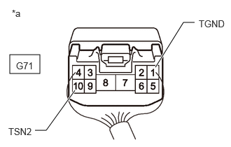
| *a | Component with harness connected
(Parking Brake Actuator Assembly with Bracket) |
Measure the voltage according to the value(s) in the table below.
- Standard Voltage:
Tester Connection Condition Specified Condition Click Location & Routing(G71)Location & Routingewd_type=routing;type=c;code=G71
Click Connector(G71)Body>Floor Wire / No. 3 Floor Wire>Parking Brake Actuator with Bracket Assemblyewd_type=component;type=c;code=G71;pinno=1,10
G71-1 (TGND) - G71-10 (TSN2) Ignition switch ON 0.35 to 4.5 V
- Result:
Proceed to OK NG
Post-procedure1
None
OK
for LHD: Click hereBrake>BRAKE CONTROL / DYNAMIC CONTROL SYSTEMS>BRAKE ACTUATOR (for LHD)>REMOVAL
for RHD: Click hereBrake>BRAKE CONTROL / DYNAMIC CONTROL SYSTEMS>BRAKE ACTUATOR (for RHD)>REMOVAL
NG