PARKING BRAKE ELECTRIC PARKING BRAKE ACTUATOR REMOVAL
CAUTION / NOTICE / HINT
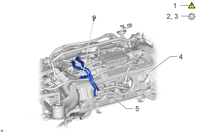
| Procedure | Part Name Code | 
|

|

|
|
|---|---|---|---|---|---|
| 1 | PRECAUTION | - | ( ) |
- | - |
| 2 | RELEASE PARKING BRAKE | - | - | - | ()
|
| 3 | FORCED RELEASE PARKING BRAKE | - | - | - | ()
|
| 4 | REAR SUSPENSION MEMBER SUB-ASSEMBLY | 51206A | - | - | |
| 5 | OIL COOLER TUBE ASSEMBLY | - | - | - | - |
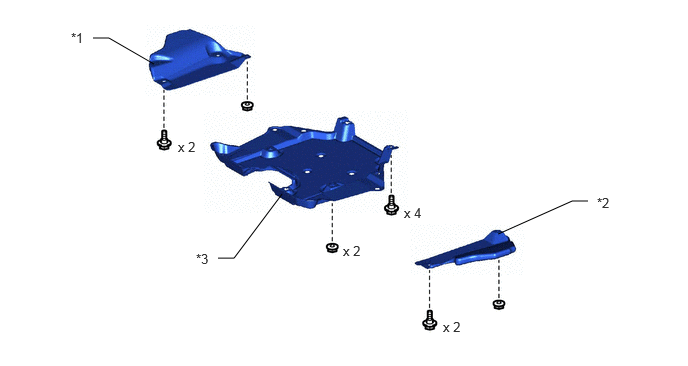
| *1 | NO. 1 DIFFERENTIAL SUPPORT PROTECTOR | *2 | NO. 2 DIFFERENTIAL SUPPORT PROTECTOR |
| *3 | REAR SUSPENSION BRACE COVER | - | - |
| Procedure | Part Name Code |
|
|
|
|
|---|---|---|---|---|---|
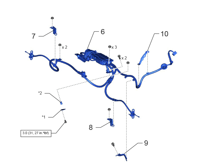
| 6 | PARKING BRAKE ACTUATOR ASSEMBLY WITH BRACKET | 46300 | - | - | - |
| 7 | CABLE SUPPORT BRACKET | 46451F | - | - | - |
| 8 | NO. 2 CABLE SUPPORT BRACKET | 46452B | - | - | - |
| 9 | NO. 2 ACTUATOR HARNESS CLAMP | 48596B | - | - | - |
| 10 | NO. 1 ACTUATOR HARNESS CLAMP | 48596A | - | - | |
| *1 | RELEASE CABLE COVER | *2 | CAP |

|
N*m (kgf*cm, ft.*lbf): Specified torque | - | - |
CAUTION / NOTICE / HINT
The necessary procedures (adjustment, calibration, initialization, or registration) that must be performed after parts are removed, installed, or replaced during the parking brake actuator with bracket assembly removal/installation are shown below.
- Necessary Procedure After Parts Removed/Installed/Replaced:
Replacement Part or Procedure Necessary Procedures Effects/Inoperative when not Performed Link *: The vehicle height changes because of suspension or tire replacement.
Disconnect cable from negative (-) auxiliary battery terminal Memorize steering angle neutral point Parking assist monitor system ( )
Panoramic view monitor system ( )
Parking brake actuator assembly with bracket ·Perform "EPB Initalize"
·Acquire tension sensor zero point
·Parking brake bedding
Electric parking brake system ( )
·Rear disc (Including removal and installation)
·Parking brake shoe (Including removal and installation)
·Parking brake actuator assembly with bracket (Removed and installed)
Parking brake bedding Suspension, tires, etc.* ·Measurement of ultrasonic sensor detection angle
·Ultrasonic sensor detection angle registration
·Parking support brake system
·Advanced park
w/ Advanced Park:
()
w/o Advanced Park:
()
Rear television camera assembly optical axis (Back camera position setting) Parking assist monitor system ( )
·Parking assist ECU initialization
·Adjust steering angle
·Rear television camera view adjustment (for Rear camera detection system)
Panoramic view monitor system ( )
Perform headlight ECU sub-assembly LH initialization Automatic headlight beam level control system ( )
- HINT:
-
When the cable is disconnected/reconnected to the auxiliary battery terminal, systems temporarily stop operating. However, each system has a function that completes learning the first time the system is used.
- ·
Learning completes when vehicle is driven
Effect/Inoperative Function When Necessary Procedures are not Performed Necessary Procedures Link Lane tracing assist system Drive the vehicle straight ahead at 35 km/h (22 mph) or more for 5 seconds or more. ( )
Pre-collision system Adaptive high beam system
·Learning completes when vehicle is operated normally
Effect/Inoperative Function When Necessary Procedures are not Performed Necessary Procedures Link Air conditioning system After the ignition switch is turned to ON, theservo motor and expansion valve standardposition is recognized. -
·Use the same procedure for the RH and LH sides.
·The procedure listed below is for the LH side.
PROCEDURE

 1. PRECAUTION
|
|
Click here()
|
2.RELEASE PARKING BRAKE
Turn off the electric parking brake AUTO function.
With the power switch on (IG), operate the electric parking brake switch assembly to release the parking brake. Then turn the power switch off.
- HINT:
-
If the parking brake cannot be released, perform the forced release of parking brake.
3.FORCED RELEASE PARKING BRAKE
|
|
|
Remove the No. 1 differential support protector.
Click hereGeneral>MAINTENANCE>Q710 HYBRID TRANSAXLE FLUID>REPLACEMENT
Remove the No. 2 differential support protector.
Click hereGeneral>MAINTENANCE>Q710 HYBRID TRANSAXLE FLUID>REPLACEMENT
Remove the rear suspension brace cover.
Click hereGeneral>MAINTENANCE>Q710 HYBRID TRANSAXLE FLUID>REPLACEMENT
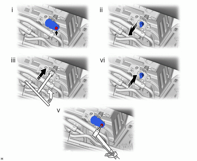
Using a 4 mm long socket hexagon wrench, remove the bolt and release cable cover.
Remove the cap.
Insert a 4 mm socket hexagon wrench into the release cable and while pushing down, rotate it counterclockwise.
After checking that the parking brake has been released, install the cap.
- NOTICE:
-
When installing the cap, make sure it inserted facing the correct direction.
Using a 4 mm long socket hexagon wrench, install the release cable cover with the bolt.
- Torque:
- 3.0 N*m (31 kgf*cm, 27 in.*lbf)
51206A
4.REMOVE REAR SUSPENSION MEMBER SUB-ASSEMBLY
5.SEPARATE OIL COOLER TUBE ASSEMBLY

46300
6.REMOVE PARKING BRAKE ACTUATOR ASSEMBLY WITH BRACKET
Remove the bolt and 6 nuts to disconnect the parking brake actuator assembly with bracket from the rear suspension member sub-assembly.
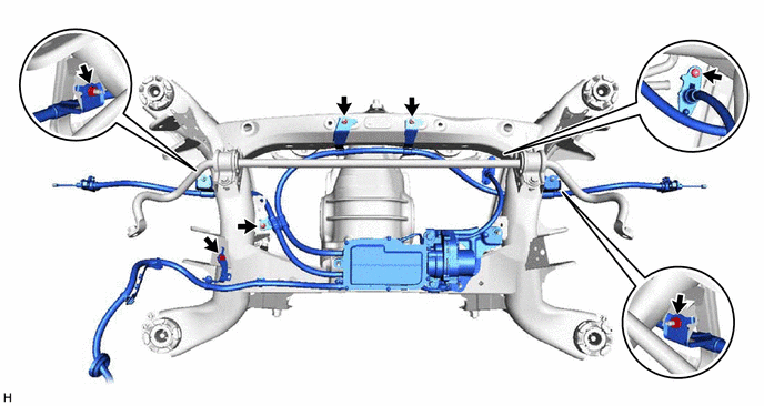
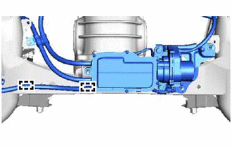
Disconnect the 2 clamps from the rear suspension member sub-assembly.
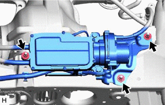
Remove the 3 nuts and parking brake actuator assembly with bracket.
46451F
7.REMOVE CABLE SUPPORT BRACKET

Remove the cable support bracket in the direction indicated by the arrow shown in the illustration.
46452B
8.REMOVE NO. 2 CABLE SUPPORT BRACKET

Remove the No. 2 cable support bracket in the direction indicated by the arrow shown in the illustration.
48596B
9.REMOVE NO. 2 ACTUATOR HARNESS CLAMP

48596A
10.REMOVE NO. 1 ACTUATOR HARNESS CLAMP