HYBRID / BATTERY CONTROL HYBRID CONTROL SYSTEM P274A1C Transmission Fluid Temperature Sensor "C" Voltage Out of Range P274A1F Transmission Fluid Temperature Sensor "C" Circuit Intermittent
DTC SUMMARY
MALFUNCTION DESCRIPTION
These DTCs are stored when the transaxle fluid temperature sensor output is abnormal. The cause of this malfunction may be one of the following:
Internal transaxle fluid temperature sensor malfunction
Open or short in transaxle fluid temperature sensor
The connectors are not connected properly
Foreign matter or water on the connector terminals
Open or short in wire harness
DESCRIPTION
Refer to the description for DTC P274A11.
Click hereEngine / Hybrid System>HYBRID / BATTERY CONTROL>HYBRID CONTROL SYSTEM>P274A11
| DTC No. | Detection Item | DTC Detection Condition | Trouble Area | Warning Indicate | DTC Output from | Priority |
|---|---|---|---|---|---|---|
| P274A1C | Transmission Fluid Temperature Sensor "C" Voltage Out of Range | Transaxle fluid temperature sensor output does not increase in which the value should increase, or output does not decrease under conditions in which the value should decrease.
(2 trip detection logic) |
·
Wire harness or connector ·
EV control ECU ·
FCV with motor transaxle assembly (Transaxle fluid temperature sensor) |
Master Warning:
Comes on |
EV | A |
| P274A1F | Transmission Fluid Temperature Sensor "C" Circuit Intermittent | Sudden change in transaxle fluid temperature sensor output or hunting:
Unusual sudden change in transaxle fluid temperature sensor output occurs and offset condition continues for a certain period of time, or unusual change in transaxle fluid temperature sensor output occurs repeatedly. (1 trip detection logic) |
·
Wire harness or connector ·
EV control ECU ·
FCV with motor transaxle assembly (Transaxle fluid temperature sensor) |
Master Warning:
Comes on |
EV | A |
| DTC No. | Data List |
|---|---|
| P274A1C | ·
FC Air Compressor Motor Temperature ·
Motor Temperature ·
Transaxle Oil Temperature |
| P274A1F | Transaxle Oil Temperature |
CONFIRMATION DRIVING PATTERN
- HINT:
-
After repair has been completed, clear the DTC and then check that the vehicle has returned to normal by performing the following All Readiness check procedure.
-
Click hereEngine / Hybrid System>HYBRID / BATTERY CONTROL>HYBRID CONTROL SYSTEM>UTILITY
Clear the DTCs (even if no DTCs are stored, perform the clear DTC procedure).
Turn the ignition switch off.
Leave the vehicle as is for 5 hours or more and then check the values of the Data List items "FC Air Compressor Motor Temperature", "Motor Temperature" and "Transaxle Oil Temperature".
Enter the following menus: Powertrain / EV / Utility / All Readiness.
Check the DTC judgment result.
- HINT:
- ·
If the judgment result shows NORMAL, the system is normal.
·If the judgment result shows ABNORMAL, the system has a malfunction.
·If the judgment result shows INCOMPLETE, perform driving pattern again.
Clear the DTCs (even if no DTCs are stored, perform the clear DTC procedure).
Turn the ignition switch off and wait for 10 minutes or more.
Turn the ignition switch to ON and wait for 5 seconds or more.
Enter the following menus: Powertrain / EV / Utility / All Readiness.
Check the DTC judgment result.
- HINT:
- ·
If the judgment result shows NORMAL, the system is normal.
·If the judgment result shows ABNORMAL, the system has a malfunction.
·If the judgment result shows INCOMPLETE, perform driving pattern again.
PROCEDURE
Pre-procedure1
None.
Procedure1
Check for DTCs.
- Powertrain > EV > Trouble Codes
- 50001 397
- Result:
Result Proceed to P274A1C or P274A1F is output and any DTCs in the table below are output A Only P274A1C or P274A1F is output B
| Relevant DTC | |
|---|---|
| P274A11 | Transmission Fluid Temperature Sensor "C" Circuit Short to Ground |
| P274A15 | Transmission Fluid Temperature Sensor "C" Circuit Short to Auxiliary Battery or Open |
Post-procedure1
Turn the ignition switch off.
A
B
Click hereEngine / Hybrid System>HYBRID / BATTERY CONTROL>HYBRID CONTROL SYSTEM>P0A2A11
- Result:
Result Proceed to OK A NG (The connector is not connected securely.) B NG (The terminals are not making secure contact or are deformed, or water or foreign matter exists in the connector.) C
A
B
C
Pre-procedure1
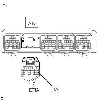
| *a | Rear view of wire harness connector
(to EV Control ECU) |
Disconnect the A15 EV control ECU connector.
Procedure1
Measure the resistance according to the value(s) in the table below.
- Standard Resistance:
Tester Connection Condition Specified Condition Click Location & Routing(A15)Location & Routingewd_type=routing;type=c;code=A15
Click Connector(A15)Instrument Panel>Front Compartment Main Wire>EV Control ECUewd_type=component;type=c;code=A15;pinno=20,28
A15-20 (TTA) - A15-28 (ETTA) Ignition switch off 1.4 to 94 kΩ
- Result:
Proceed to OK NG
Post-procedure1
Reconnect the A15 EV control ECU connector.
OK
NG
Click hereEngine / Hybrid System>HYBRID / BATTERY CONTROL>HYBRID CONTROL SYSTEM>P0A2A11
- Result:
Result Proceed to OK A NG (The connector is not connected securely.) B NG (The terminals are not making secure contact or are deformed, or water or foreign matter exists in the connector.) C
A
B
C
Pre-procedure1
Remove the AG2 No. 2 floor wire connector.
Disconnect the A15 EV control ECU connector.
Procedure1
Measure the resistance according to the value(s) in the table below.
- Standard Resistance:
Tester Connection Condition Specified Condition Click Location & Routing(AG2,A15)Location & Routingewd_type=routing;type=w,c;code=AG2,A15
Click Connector(AG2)Instrument Panel>Front Compartment Main Wire>Front Compartment Main Wire and Floor Wireewd_type=component;type=w;code=AG2;pinno=17,18
Click Connector(A15)Instrument Panel>Front Compartment Main Wire>EV Control ECUewd_type=component;type=c;code=A15;pinno=20,28
AG2-17 (TTA) - A15-20 (TTA) Ignition switch off Below 1 Ω AG2-18 (ETTA) - A15-28 (ETTA) Ignition switch off Below 1 Ω AG2-17 (TTA) or A15-20 (TTA) - Body ground and other terminals Ignition switch off 10 kΩ or higher AG2-18 (ETTA) or A15-28 (ETTA) - Body ground and other terminals Ignition switch off 10 kΩ or higher
- Result:
Proceed to OK NG
Post-procedure1
Reconnect the A15 EV control ECU connector.
Install the AG2 No. 2 floor wire connector.
OK
NG
Click hereEngine / Hybrid System>HYBRID / BATTERY CONTROL>HYBRID CONTROL SYSTEM>P0A2A11
- Result:
Result Proceed to OK A NG (The connector is not connected securely.) B NG (The terminals are not making secure contact or are deformed, or water or foreign matter exists in the connector.) C
A
B
C
Pre-procedure1
Remove the AG2 No. 2 floor wire connector.
Remove the GG2 No. 3 floor wire connector.
Procedure1
Measure the resistance according to the value(s) in the table below.
- Standard Resistance:
Tester Connection Condition Specified Condition Click Location & Routing(AG2,GG2)Location & Routingewd_type=routing;type=w,w;code=AG2,GG2
Click Connector(AG2)Instrument Panel>Front Compartment Main Wire>Front Compartment Main Wire and Floor Wireewd_type=component;type=w;code=AG2;pinno=17,18
Click Connector(GG2)Body>Floor Wire / No. 3 Floor Wire>No. 3 Floor Wire and Floor Wireewd_type=component;type=w;code=GG2;pinno=15,16
AG2-17 (TTA) - GG2-15 (TTA) Ignition switch off Below 1 Ω AG2-18 (ETTA) - GG2-16 (ETTA) Ignition switch off Below 1 Ω AG2-17 (TTA) or GG2-15 (TTA) - Body ground and other terminals Ignition switch off 10 kΩ or higher AG2-18 (ETTA) or GG2-16 (ETTA) - Body ground and other terminals Ignition switch off 10 kΩ or higher
- Result:
Proceed to OK NG
Post-procedure1
Remove the GG2 No. 3 floor wire connector.
Install the AG2 No. 2 floor wire connector.
OK
NG
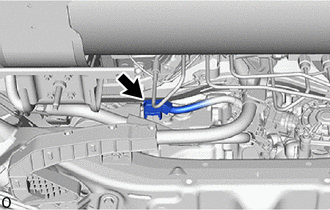
Check the connection condition of the transaxle fluid temperature sensor connector and the contact pressure of each terminal. Check the terminals for deformation, and check the connector for water ingress and foreign matter.
- HINT:
- OK:
- The connector is connected securely.
- The terminals are not deformed and are connected securely.
- No water or foreign matter in the connector.
- Result:
Result Proceed to OK A NG (The connector is not connected securely.) B NG (The terminals are not making secure contact or are deformed, or water or foreign matter exists in the connector.) C
A
B
C
Pre-procedure1
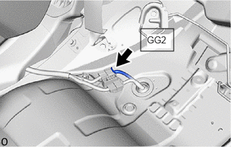
Remove the GG2 No. 3 floor wire connector.
Disconnect the G154 FCV with motor transaxle assembly connector.
Procedure1
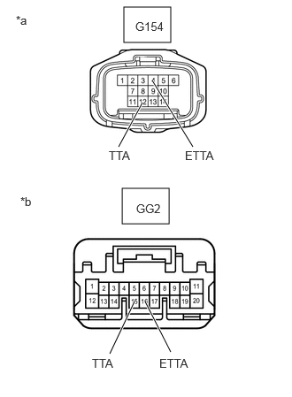
| *a | Fron view of wire harness connector
(to FCV With Motor Transaxle Assembly) |
| *b | Fron view of wire harness connector
(No. 3 Floor Wire Connector) |
Measure the resistance according to the value(s) in the table below.
- Standard Resistance:
Tester Connection Condition Specified Condition Click Location & Routing(GG2,G154)Location & Routingewd_type=routing;type=w,c;code=GG2,G154
Click Connector(GG2)Body>Floor Wire / No. 3 Floor Wire>No. 3 Floor Wire and Floor Wireewd_type=component;type=w;code=GG2;pinno=15,16
Click Connector(G154)Body>Floor Wire / No. 3 Floor Wire>FCV Transaxle with Motor Assemblyewd_type=component;type=c;code=G154;pinno=12,4
GG2-15 (TTA) - G154-12 (TTA) Ignition switch off Below 1 Ω GG2-16 (ETTA) - G154-4 (ETTA) Ignition switch off Below 1 Ω GG2-15 (TTA) or G154-12 (TTA) - Body ground and other terminals Ignition switch off 10 kΩ or higher GG2-16 (ETTA) or G154-4 (ETTA) - Body ground and other terminals Ignition switch off 10 kΩ or higher
- Result:
Proceed to OK NG
Post-procedure1
Reconnect the G154 FCV with motor transaxle assembly connector.
Install the GG2 No. 3 floor wire connector.
OK
NG
Pre-procedure1
None.
Procedure1
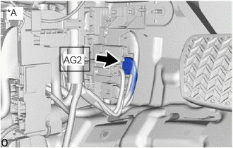
| *A | for LHD |
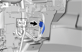
| *A | for RHD |
Remove the AG2 No. 2 floor wire connector.
- Standard Resistance:
Tester Connection Condition Specified Condition Click Location & Routing(AG2)Location & Routingewd_type=routing;type=w;code=AG2
Click Connector(AG2)Instrument Panel>Front Compartment Main Wire>Front Compartment Main Wire and Floor Wireewd_type=component;type=w;code=AG2;pinno=17,18
AG2-17 (TTA) - AG2-18 (ETTA) Ignition switch off 1.4 to 94 kΩ
- Result:
Proceed to OK NG
Post-procedure1
Install the AG2 No. 2 floor wire connector.
OK
NG
Pre-procedure1
Remove the GG2 No. 3 floor wire connector.
Procedure1
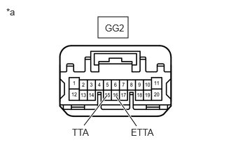
| *a | Fron view of wire harness connector
(No. 3 Floor Wire Connector) |
Measure the resistance according to the value(s) in the table below.
- Standard Resistance:
Tester Connection Condition Specified Condition Click Location & Routing(GG2)Location & Routingewd_type=routing;type=w;code=GG2
Click Connector(GG2)Body>Floor Wire / No. 3 Floor Wire>No. 3 Floor Wire and Floor Wireewd_type=component;type=w;code=GG2;pinno=15,16
GG2-15 (TTA) - GG2-16 (ETTA) Ignition switch off 1.4 to 94 kΩ
- Result:
Proceed to OK NG
Post-procedure1
Install the GG2 No. 3 floor wire connector.
OK
NG
Pre-procedure1
Disconnect the G154 FCV with motor transaxle assembly connector.
Procedure1
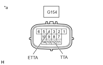
| *a | Fron view of wire harness connector
(to FCV With Motor Transaxle Assembly) |
Measure the resistance according to the value(s) in the table below.
- Standard Resistance:
Tester Connection Condition Specified Condition Click Location & Routing(G154)Location & Routingewd_type=routing;type=c;code=G154
Click Connector(G154)Body>Floor Wire / No. 3 Floor Wire>FCV Transaxle with Motor Assemblyewd_type=component;type=c;code=G154;pinno=12,4
G154-12 (TTA) - G154-4 (ETTA) Ignition switch off 1.4 to 94 kΩ
- Result:
Proceed to OK NG
Post-procedure1
Reconnect the G154 FCV with motor transaxle assembly connector.
OK
NG