FUEL FUEL SYSTEM DISCHARGE COMPRESSED HYDROGEN GAS
CAUTION / NOTICE / HINT
- HINT:
-
These procedures are only performed when discharging compressed hydrogen gas from the hydrogen tank assemblies.
- CAUTION:
- ·
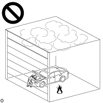
When discharging pressurized hydrogen gas from the hydrogen tank assembly, do not perform the procedure in an indoor area with poor ventilation.
·Accumulated hydrogen gas could ignite, resulting in a serious accident.
- ·
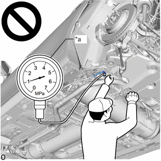 1.083,1.229 1.406,0.833 1.406,0.833 1.573,0.833 false 1.604,0.75 1.854,0.927 0.25,0.177 10 true *a
*a When inside of piping is pressurized
Do not install or remove any hydrogen system components without first performing depressurization procedures.
·The highly pressurized hydrogen gas inside the hydrogen tank assembly could blow out, resulting in a serious accident.
- ·
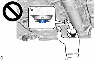 1.083,0.271 1.323,0.469 0.24,0.198 10 true *a
*a Manual Valve Open
Do not perform depressurization procedures when the manual valve of the hydrogen tank assembly is open.
·The highly pressurized hydrogen gas inside the hydrogen tank assembly could blow out, resulting in a serious accident.
- ·
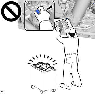
When performing depressurization, do not perform procedures by hand without wearing protective glasses and gloves.
·The highly pressurized hydrogen gas inside the hydrogen tank assembly could blow out, resulting in a serious accident.
- ·
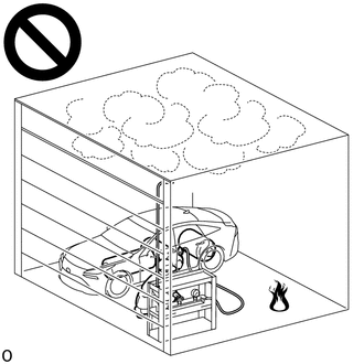
When discharging pressurized hydrogen gas from the hydrogen tank assembly, do not perform the procedure in an indoor area with poor ventilation.
·Accumulated hydrogen gas could ignite, resulting in a serious accident.
- ·
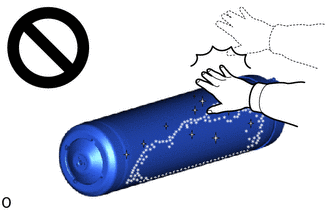
While discharging pressurized hydrogen gas, the temperature inside the tank decreases and frost may form on the outside. Do not touch tanks, piping, or SST (hydrogen venting tool) when frost has formed on them.
·Touching tanks, piping, or SST (hydrogen venting tool) on which frost has formed could result in burn-like injuries due to frostbite.
- ·
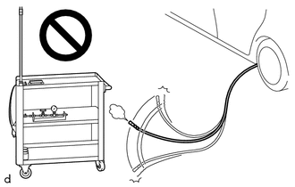
When opening the tank shut valve and applying pressure to SST (hydrogen venting tool), stay away from SST (flexible hose).
·If SST (flexible hose) comes off, you could be struck by the loose end of SST (flexible hose), causing a serious accident.
- NOTICE:
- ·
After turning the ignition switch off, waiting time may be required before disconnecting the cable from the negative (-) auxiliary battery terminal.
Click hereGeneral>SETUP>WHEN DISCONNECTING OR RECONNECTING BATTERY TERMINAL>BEFORE DISCONNECTING BATTERY
·When performing depressurization, do not open or close any parts of the hydrogen gas piping except for the following:
- Adjustment bolt of the hydrogen tank assembly manual valve
- Tank shut valve of the hydrogen tank assembly
- No. 1 hydrogen supply regulator plug
·Place signs [HIGH PRESSURE GAS WORK IN PROGRESS - DO NOT TOUCH!], etc. to warn other technicians to be cautious. (An example sign is included, so make a copy and use it.)
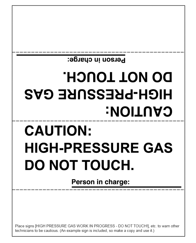 0.552,8.167 6.667,8.51 6.115,0.344 10 false Place signs [HIGH PRESSURE GAS WORK IN PROGRESS - DO NOT TOUCH!], etc. to warn other technicians to be cautious. (An example sign is included, so make a copy and use it.)
OVERVIEW OF COMPRESSED HYDROGEN GAS DISCHARGE PROCEDURE
The compressed hydrogen gas discharging procedures are divided into some main processes, and the following procedure is an overview of the compressed hydrogen gas discharging procedures.
Open the medium pressure leak check port and release the compressed hydrogen gas that is inside the piping into the atmosphere.
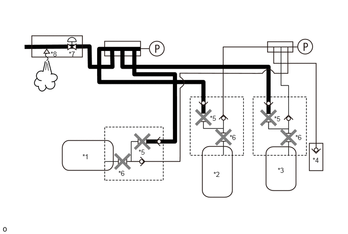
| *1 | No. 1 Hydrogen Tank Assembly | *2 | No. 2 Hydrogen Tank Assembly |
| *3 | No. 3 Hydrogen Tank Assembly | *4 | Hydrogen Inlet Receptacle Assembly |
| *5 | Tank Shut Valve | *6 | Manual Valve |
| *7 | Hydrogen Supply Regulator | *8 | Medium Pressure Leak Check Port |
Using the small amount of hydrogen remaining in the shaded area shown in the illustration, inspect the connecting portions of SST (hydrogen venting tool) for compressed hydrogen gas leaks.
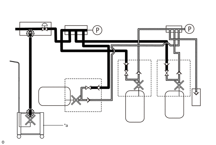
| *a | SST (Hydrogen Venting Tool) | - | - |

|
Connecting Portions | - | - |
Using the compressed hydrogen gas inside the hydrogen tank (maximum 70 MPa (713.8 kgf/cm2, 10150 psi)), inspect the connecting portions of SST (hydrogen venting tool) for compressed hydrogen gas leaks.
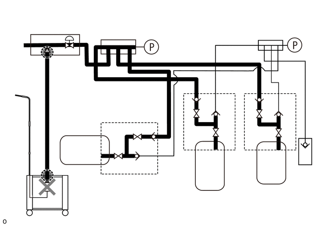
|
|
Connecting Portions | - | - |
Open the valve of SST (hydrogen venting tool), and discharge the compressed hydrogen gas from the hydrogen tank.
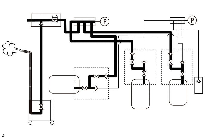
PROCEDURE

 1.CHECK DTC OUTPUT
Check for DTCs.
- NOTICE:
-
If DTCs are output, perform troubleshooting for each DTC.
58404B
2.REMOVE REAR NO. 4 FLOOR BOARD SUB-ASSEMBLY
58403L
3.REMOVE REAR NO. 3 FLOOR BOARD SUB-ASSEMBLY
58402K
4.REMOVE NO. 2 FLOOR BOARD SUB-ASSEMBLY
57628E
5.REMOVE REAR FLOOR SIDE MEMBER COVER LH
58398F
6.REMOVE NO. 1 FLOOR UNDER COVER
7.PREPARE SST (HYDROGEN VENTING TOOL)
- HINT:
- Before performing work, check the set up conditions of SST (hydrogen venting tool).
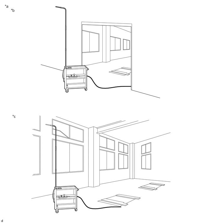 0.385,0.281 0.698,0.438 0.313,0.156 10 false *b 0.438,4.021 0.75,4.177 0.313,0.156 10 false *c 0.167,0.135 0.479,0.292 0.313,0.156 10 false *a
*a Hydrogen Gas Discharging Conditions *b Basic Conditions *c Other than Basic Conditions (if mechanism cannot be set up outdoors) - -
Check the assembly of SST (hydrogen venting tool).
- SST
- 09404-62010 (09404-06010, 09404-06020, 09404-06030, 09404-06040, 09404-06050, 09404-06060)
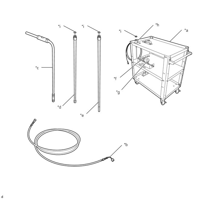
| *a | SST (Venting Stand) | *b | SST (Flexible Hose) |
| *c | SST (Upper Release Pipe) | *d | SST (Middle Release Pipe) |
| *e | SST (Lower Release Pipe) | *f | Open/close Valve |
| *g | Pressure Gauge | *h | Discharge Pipe Support |
| *i | SST (O-ring (Replace at time of using SST (hydrogen venting tool))) | - | - |
Make sure to replace SST (3 O-rings) of SST (hydrogen venting tool) with new ones.
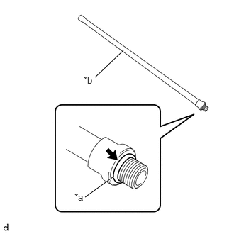
| *a | SST (O-ring) |
| *b | SST (Middle Release Pipe) |
Remove SST (O-ring) from SST (middle release pipe).
- SST
- 09404-62010 (09404-06060, 09404-06040)
Install a new SST (O-ring) to SST (middle release pipe).
- SST
- 09404-62010 (09404-06040, 09404-06060)
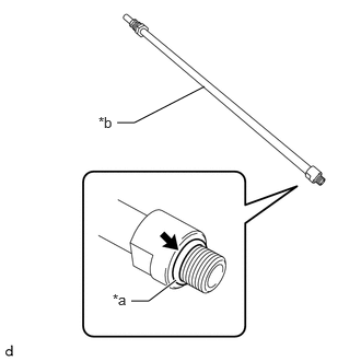
| *a | SST (O-ring) |
| *b | SST (Lower Release Pipe) |
Remove SST (O-ring) from SST (lower release pipe).
- SST
- 09404-62010 (09404-06050, 09404-06060)
Install a new SST (O-ring) to SST (lower release pipe).
- SST
- 09404-62010 (09404-06050, 09404-06060)
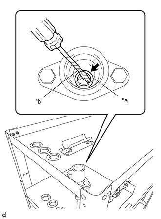
| *a | SST (O-ring) |
| *b | Protective Tape |
Using a thin-bladed screwdriver with its tip wrapped in protective tape, remove SST (O-ring) from the release pipe support.
- SST
- 09404-62010 (09404-06010, 09404-06060)
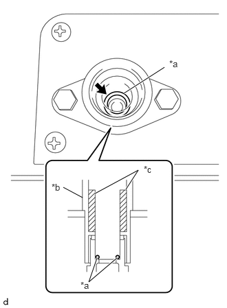
| *a | SST (O-ring) |
| *b | Release Pipe Support |
| *c | Collar |
As shown in the illustration, install a new SST (O-ring) to the release pipe support.
- SST
- 09404-62010 (09404-06060)
Connect each part of SST (hydrogen venting tool) and prepare it for use.
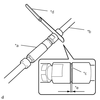
| *a | SST (Upper Release Pipe) |
| *b | SST (Middle Release Pipe) |
| *c | SST (O-ring) |
| *d | Thickness Gauge |
| *e | 1.7 mm (0.0669 in.) |
Connect SST (upper release pipe) and SST (middle release pipe), and using a thickness gauge, measure the clearance in the location shown in the illustration.
- SST
- 09404-62010 (09404-06030, 09404-06040, 09404-06060)
- Discharge pipe connection clearance:
1.7 mm (0.0669 in.)
- NOTICE:
-
Perform the procedure by hand. Do not use any tools.
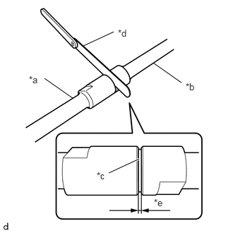
| *a | SST (Middle Release Pipe) |
| *b | SST (Lower Release Pipe) |
| *c | SST (O-ring) |
| *d | Thickness Gauge |
| *e | 1.7 mm (0.0669 in.) |
Connect SST (middle release pipe) and SST (lower release pipe), and using a thickness gauge, measure the clearance in the location shown in the illustration.
- SST
- 09404-62010 (09404-06040, 09404-06050, 09404-06060)
- Discharge pipe connection clearance:
1.7 mm (0.0669 in.)
- NOTICE:
-
Perform the procedure by hand. Do not use any tools.
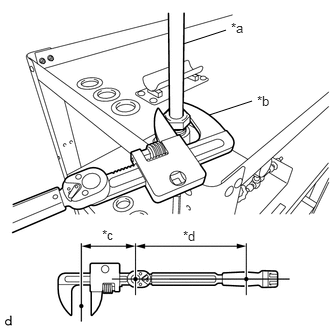
| *a | SST (Lower Release Pipe) |
| *b | SST (Variable Open Wrench) |
| *c | SST Fulcrum Length |
| *d | Torque Wrench Fulcrum Length |
Connect SST (lower release pipe) to the release pipe support, and using SST (variable open wrench), tighten the nut.
- SST
- 09922-10010
09404-62010 (09404-06050)
- Torque:
- Specified tightening torque : 20 N*m (204 kgf*cm, 15 ft.*lbf)
- HINT:
- ·
Calculate the torque wrench reading when changing the fulcrum length of the torque wrench.
Click hereGeneral>INTRODUCTION>REPAIR INSTRUCTION>PRECAUTION
·When using SST (fulcrum length of 136 mm (5.35 in.)) + torque wrench (fulcrum length of 180 mm (7.09 in.)):
11.4 N*m (116 kgf*cm, 8 ft.*lbf)
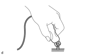
Connect the ground wire.
- NOTICE:
-
Connect the ground wire to somewhere that will enable secure electrical grounding.
8.CONNECT SST (HYDROGEN VENTING TOOL)
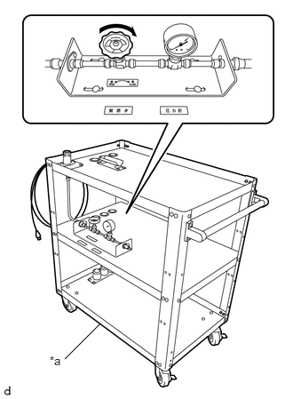
| *a | SST (Venting Stand) |
Check that the open/close valve of SST (venting stand) is closed.
- SST
- 09404-62010 (09404-06010)
Remove the No. 3 FC exhaust pipe.
Click hereEngine / Hybrid System>INTAKE / EXHAUST>EXHAUST PIPE>REMOVAL
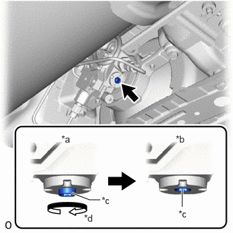
| *a | Manual Valve Open |
| *b | Manual Valve Closed |
| *c | Adjustment Bolt |
| *d | Clockwise |
Using an 8 mm hexagon socket wrench, rotate the adjustment bolt clockwise to close the manual valve of the No. 1 hydrogen tank assembly.
- Torque:
- 25 N*m (255 kgf*cm, 18 ft.*lbf)
- NOTICE:
- ·
The manual valve shuts off the pressure from the hydrogen tank assembly, so be careful not to damage the hexagonal portion.
·If the hexagonal portion has been damaged, the No. 1 hydrogen tank assembly must be replaced.
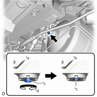
| *a | Manual Valve Open |
| *b | Manual Valve Closed |
| *c | Adjustment Bolt |
| *d | Clockwise |
Using an 8 mm hexagon socket wrench, rotate the adjustment bolt clockwise to close the manual valve of the No. 2 hydrogen tank assembly.
- Torque:
- 25 N*m (255 kgf*cm, 18 ft.*lbf)
- NOTICE:
- ·
The manual valve shuts off the pressure from the hydrogen tank assembly, so be careful not to damage the hexagonal portion.
·If the hexagonal portion has been damaged, the No. 2 hydrogen tank assembly must be replaced.
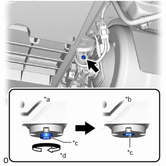
| *a | Manual Valve Open |
| *b | Manual Valve Closed |
| *c | Adjustment Bolt |
| *d | Clockwise |
Using an 8 mm hexagon socket wrench, rotate the adjustment bolt clockwise to close the manual valve of the No. 3 hydrogen tank assembly.
- Torque:
- 25 N*m (255 kgf*cm, 18 ft.*lbf)
- NOTICE:
- ·
The manual valve shuts off the pressure from the hydrogen tank assembly, so be careful not to damage the hexagonal portion.
·If the hexagonal portion has been damaged, the No. 3 hydrogen tank assembly must be replaced.
Before starting the depressurization procedure, first check that there is no mud or other contaminant around the medium pressure leak check port of the hydrogen supply regulator, and clean it as necessary.
- HINT:
-
Installing the No. 1 hydrogen supply regulator plug while any foreign matter adheres to it can cause a hydrogen gas leak.
Perform depressurization.
Make sure that the manual valves of the No. 1 hydrogen tank assembly, No. 2 hydrogen tank assembly and No. 3 hydrogen tank assembly are closed.
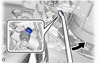
Slowly loosen the No. 1 hydrogen supply regulator plug until the hissing sound of gas escaping can be heard, then stop loosening the No. 1 hydrogen supply regulator plug and wait for the sound to stop. Repeat this procedure multiple times until the sound stops occurring, in order to depressurize the compressed hydrogen gas from the medium pressure leak check port of the hydrogen supply regulator.
- CAUTION:
-
1.083,0.271 1.323,0.469 0.24,0.198 10 true *a
*a Manual Valve Open
- ·
Do not perform depressurization procedures when the manual valve of the hydrogen tank assembly is open.
·The highly pressurized hydrogen gas inside the hydrogen tank assembly could blow out, resulting in a serious accident.
- ·
When performing depressurization, do not perform procedures by hand without wearing protective glasses and gloves.
·The highly pressurized hydrogen gas inside the hydrogen tank assembly could blow out, resulting in a serious accident.
- NOTICE:
-
When performing depressurization, only loosen the No. 1 hydrogen supply regulator plug. Do not remove it.
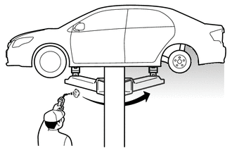
Blow compressed air at the underside of the vehicle to disperse any accumulated hydrogen gas.
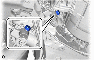
Remove the No. 1 hydrogen supply regulator plug from the hydrogen supply regulator.
- NOTICE:
-
When frost has formed on the hydrogen tank assembly or piping, water droplets may be formed when the frost begins to melt. If water droplets enter the tank or piping, it could result in blockage of the hydrogen piping, so do not allow water droplets to enter the tank or piping.
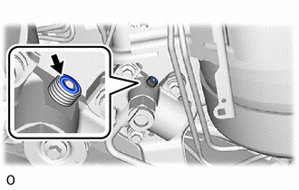
Remove the O-ring from the hydrogen supply regulator.
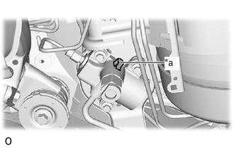
| *a | Protective Tape |
To prevent damage to the seal portions and threaded portions, and to prevent foreign matter such as dust or metal fragments from entering the openings, cover the seal portions, threaded portions, and openings of the hydrogen supply regulator with protective tape.
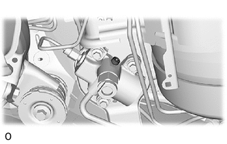
To prevent damage to the seal portions and threaded portions, and to prevent foreign matter such as dust or metal fragments from entering the openings, do not remove the protective tape covering the seal portions, threaded portions, and openings of the hydrogen supply regulator until immediately before performing work.
- NOTICE:
-
When frost has formed on the hydrogen tank assembly or piping, water droplets may be formed when the frost begins to melt. If water droplets enter the tank or piping, it could result in blockage of the hydrogen piping, so do not allow water droplets to enter the tank or piping.
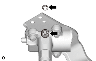
Apply TOYOTA Genuine FC Grease to a new O-ring and to the threaded portion of the hydrogen supply regulator.
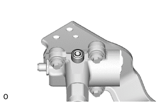
Install the O-ring to the hydrogen supply regulator.
- NOTICE:
-
During installation, make sure not to damage the O-ring.
Connect SST (hydrogen venting tool).
- SST
- 09404-62010 (09404-06010, 09404-06020, 09404-06030, 09404-06040, 09404-06050)
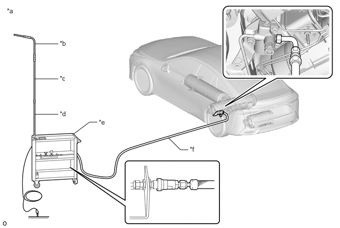
| *a | Concept of SST (hydrogen venting tool) Connection | *b | SST (Upper Release Pipe) |
| *c | SST (Middle Release Pipe) | *d | SST (Lower Release Pipe) |
| *e | SST (Venting Stand) | *f | SST (Flexible Hose) |
- HINT:
-
There are 2 types of SST (flexible hose).
 4.531,0.125 4.844,0.281 0.313,0.156 10 false *b 1.979,0.104 2.292,0.26 0.313,0.156 10 false *a
*a Type A *b Type B
for Type A:
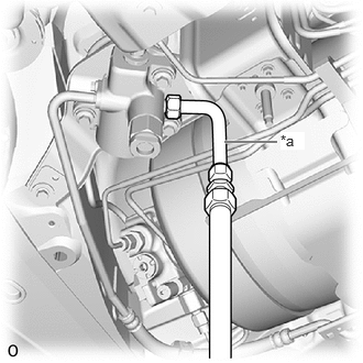
| *a | SST (Flexible Hose) |
Temporarily install SST (flexible hose) to the hydrogen supply regulator.
- SST
- 09404-62010 (09404-06020)
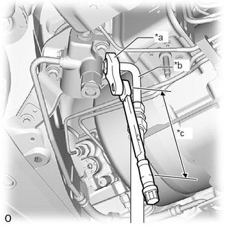
| *a | SST (Open End Wrench) |
| *b | SST (Flexible Hose) |
| *c | Specified tightening torque |
Using SST(open end wrench), tighten SST (flexible hose).
- SST
- 09404-62010 (09404-06020)
09922-10240
- Torque:
- Specified tightening torque:
9.0 N*m (92 kgf*cm, 80 in.*lbf)
- NOTICE:
- ·
Make sure that SST (flexible hose) does not interfere with part of the vehicle.
·If SST (flexible hose) interferes with any part of the vehicle, protect it with a piece of cloth, etc.
- HINT:
- ·
Calculate the torque wrench reading when changing the fulcrum length of the torque wrench.
Click hereGeneral>INTRODUCTION>REPAIR INSTRUCTION>PRECAUTION
·When using SST (fulcrum length of 40 mm (1.57 in.)) + torque wrench (fulcrum length of 162 mm (6.38 in.)): 7.2 N*m (73 kgf*cm, 64 in.*lbf)
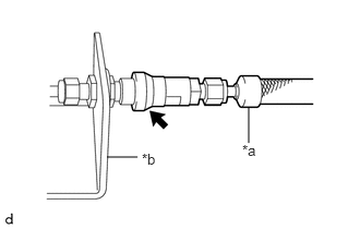
| *a | SST (Flexible Hose) |
| *b | SST (Venting Stand) |
Connect SST (flexible hose) to SST (Venting Stand).
- SST
- 09404-62010 (09404-06010, 09404-06020)
for Type B:
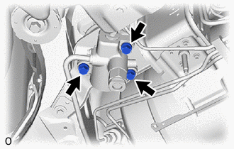
Remove the 3 bolts of the hydrogen supply regulator.
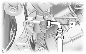
| *a | SST (Flexible Hose) |
Temporarily install SST (flexible hose) to the hydrogen supply regulator.
- SST
- 09404-62010 (09404-06020)
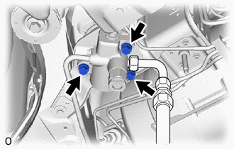
Install the hydrogen supply regulator with the 3 bolts.
- Torque:
- 16.5 N*m (168 kgf*cm, 12 ft.*lbf)
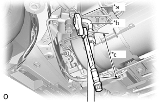
| *a | SST (Open End Wrench) |
| *b | SST (Flexible Hose) |
| *c | Specified tightening torque |
Using SST(open end wrench), tighten SST (flexible hose).
- SST
- 09404-62010 (09404-06020)
09922-10240
- Torque:
- Specified tightening torque:
9.0 N*m (92 kgf*cm, 80 in.*lbf)
- NOTICE:
- ·
Make sure that SST (flexible hose) does not interfere with part of the vehicle.
·If SST (flexible hose) interferes with any part of the vehicle, protect it with a piece of cloth, etc.
- HINT:
- ·
Calculate the torque wrench reading when changing the fulcrum length of the torque wrench
Click hereGeneral>INTRODUCTION>REPAIR INSTRUCTION>PRECAUTION
·When using SST (fulcrum length of 40 mm (1.57 in.)) + torque wrench (fulcrum length of 162 mm (6.38 in.)): 7.2 N*m (73 kgf*cm, 64 in.*lbf)
| *a | SST (Flexible Hose) |
| *b | SST (Venting Stand) |
Connect SST (flexible hose) to SST (Venting Stand).
- SST
- 09404-62010 (09404-06010, 09404-06020)
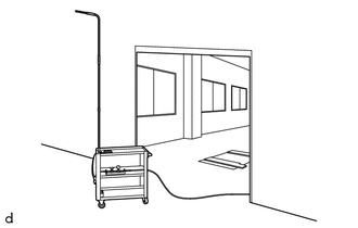
Under basic conditions
Set SST (hydrogen venting tool) in an outdoor location.
- NOTICE:
-
Take care that the compressed hydrogen gas that is discharged during the discharging procedure does not enter any indoor location.
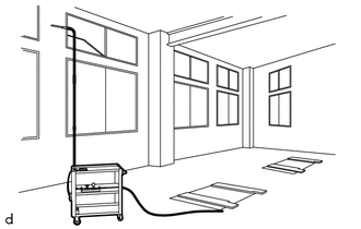
Other than basic conditions (when outdoor setup is not possible)
When SST (hydrogen venting tool) will be set up indoors, locate it along a wall near a window, and with the tip of SST (upper release pipe) outdoors.
- NOTICE:
-
Open windows on two sides or more, and ensure that there is adequate ventilation to prevent the compressed hydrogen gas that is discharged from collecting inside.
Open the tank shut valves of the No. 1 hydrogen tank assembly, No. 2 hydrogen tank assembly No. 3 hydrogen tank assembly, and after 2 to 3 seconds, close the tank shut valves again.
- CAUTION:
-
- ·
When opening the tank shut valve and applying pressure to SST (hydrogen venting tool), stay away from SST (flexible hose).
·If SST (flexible hose) comes off, you could be struck by the loose end of SST (flexible hose), causing a serious accident.
- NOTICE:
-
If the Data List item "Medium-range Hydrogen Pressure (gauge)" decreases to below 0.7 MPa (7.1 kgf/cm2, 102 psi) the tank shut valves of the No. 1 hydrogen tank assembly, No. 2 hydrogen tank assembly and No. 3 hydrogen tank assembly will forcibly close.
If the tank shut valves of the No. 1 hydrogen tank assembly, No. 2 hydrogen tank assembly and No. 3 hydrogen tank assembly do not open, open the tank shut valves again, and after 2 to 3 seconds, close the tank shut valves.
Perform preliminary leak check (using remaining piping pressure).
- HINT:
-
Perform leak check using the pressure remaining upstream of the tank shut valve.
If there are any water droplets, etc. adhering to the measurement locations, wipe them away before performing the procedure.
- NOTICE:
-
Performing the measurement while any water droplets, etc. are adhering could damage the hydrogen gas detector.
Using SST and a hydrogen gas detector, inspect for leaks in the locations shown in the illustration.
- SST
- 09401-62020
- Specified Value:
Less than 500 ppm
- NOTICE:
-
If any values are outside the specified range, disconnect those locations that have leaks and assemble the parts again.
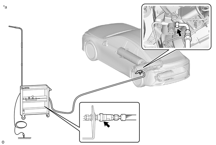
| *a | Locations to Check for Leaks | - | - |

|
Leak Check Location | - | - |
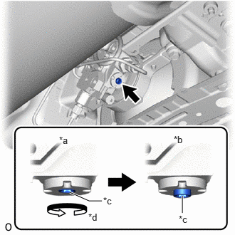
| *a | Manual Valve Closed |
| *b | Manual Valve Open |
| *c | Adjustment Bolt |
| *d | Counterclockwise |
Using an 8 mm socket hexagon wrench, rotate the adjustment bolt counterclockwise, and open the No. 1 hydrogen tank assembly manual valve.
- NOTICE:
- ·
The manual valve shuts off the pressure from the hydrogen tank assembly, so be careful not to damage the hexagonal portion.
·If the hexagonal portion is damaged, it will be impossible to operate the adjustment bolt.
·Do not rotate the adjustment bolt more than 4 rotations.
·Rotating the adjustment bolt more than 4 rotations could damage the manual valve.
·If the manual valve is damaged, it will be necessary to replace the No. 1 hydrogen tank assembly.
- HINT:
-
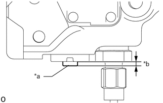 0.917,1.625 1.094,1.625 1.094,1.625 1.448,1.385 false 0.719,1.531 1.031,1.688 0.313,0.156 10 false *a 3.021,1.271 3.25,1.427 0.229,0.156 10 false *b
*a Adjustment Bolt *b Protrusion
-
When the manual valve is opened, the protrusion of the adjustment bolt is 3.5 mm (0.138 in.) or less.
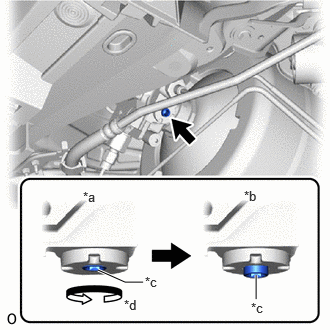
| *a | Manual Valve Closed |
| *b | Manual Valve Open |
| *c | Adjustment Bolt |
| *d | Counterclockwise |
Using an 8 mm socket hexagon wrench, rotate the adjustment bolt counterclockwise, and open the No. 2 hydrogen tank assembly manual valve.
- NOTICE:
- ·
The manual valve shuts off the pressure from the hydrogen tank assembly, so be careful not to damage the hexagonal portion.
·If the hexagonal portion is damaged, it will be impossible to operate the adjustment bolt.
·Do not rotate the adjustment bolt more than 4 rotations.
·Rotating the adjustment bolt more than 4 rotations could damage the manual valve.
·If the manual valve is damaged, it will be necessary to replace the No. 2 hydrogen tank assembly.
- HINT:
-
0.917,1.625 1.094,1.625 1.094,1.625 1.448,1.385 false 0.719,1.531 1.031,1.688 0.313,0.156 10 false *a 3.021,1.271 3.25,1.427 0.229,0.156 10 false *b
*a Adjustment Bolt *b Protrusion
-
When the manual valve is opened, the protrusion of the adjustment bolt is 3.5 mm (0.138 in.) or less.
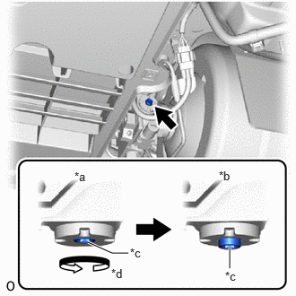
| *a | Manual Valve Closed |
| *b | Manual Valve Open |
| *c | Adjustment Bolt |
| *d | Counterclockwise |
Using an 8 mm socket hexagon wrench, rotate the adjustment bolt counterclockwise, and open the No. 3 hydrogen tank assembly manual valve.
- NOTICE:
- ·
The manual valve shuts off the pressure from the hydrogen tank assembly, so be careful not to damage the hexagonal portion.
·If the hexagonal portion is damaged, it will be impossible to operate the adjustment bolt.
·Do not rotate the adjustment bolt more than 4 rotations.
·Rotating the adjustment bolt more than 4 rotations could damage the manual valve.
·If the manual valve is damaged, it will be necessary to replace the No. 3 hydrogen tank assembly.
- HINT:
-
0.917,1.625 1.094,1.625 1.094,1.625 1.448,1.385 false 0.719,1.531 1.031,1.688 0.313,0.156 10 false *a 3.021,1.271 3.25,1.427 0.229,0.156 10 false *b
*a Adjustment Bolt *b Protrusion
-
When the manual valve is opened, the protrusion of the adjustment bolt is 3.5 mm (0.138 in.) or less.
Open the tank shut valves of the No. 1 hydrogen tank assembly, No. 2 hydrogen tank assembly No. 3 hydrogen tank assembly, and after 2 to 3 seconds, close the tank shut valves again.
- CAUTION:
-
- ·
When opening the tank shut valve and applying pressure to SST (hydrogen venting tool), stay away from SST (flexible hose).
·If SST (flexible hose) comes off, you could be struck by the loose end of SST (flexible hose), causing a serious accident.
- NOTICE:
-
If the Data List item "Medium-range Hydrogen Pressure (gauge)" decreases to below 0.7 MPa (7.1 kgf/cm2, 102 psi) the tank shut valves of the No. 1 hydrogen tank assembly, No. 2 hydrogen tank assembly and No. 3 hydrogen tank assembly will forcibly close.
If the tank shut valves of the No. 1 hydrogen tank assembly, No. 2 hydrogen tank assembly and No. 3 hydrogen tank assembly do not open, open the tank shut valves again, and after 2 to 3 seconds, close the tank shut valves.
Perform preliminary leak check (using tank pressure)
- HINT:
-
Perform leak check while applying hydrogen tank pressure.
Using SST and a hydrogen gas detector, inspect for leaks in the locations shown in the illustration.
- SST
- 09401-62020
- Specified Value:
Less than 500 ppm
- NOTICE:
- ·
If any values are outside the specified range, disconnect those locations that have leaks and assemble the parts again.
·After reassembling the locations that were leaking, perform the leak check again.
| *a | Locations to Check for Leaks | - | - |
|
|
Leak Check Location | - | - |
9.DRAIN COMPRESSED HYDROGEN GAS
- CAUTION:
- ·
While discharging pressurized hydrogen gas, the temperature inside the tank decreases and frost may form on the outside. Do not touch tanks, piping, or SST (hydrogen venting tool) when frost has formed on them.
·Touching tanks, piping, or SST (hydrogen venting tool) on which frost has formed could result in burn-like injuries due to frostbite.
- NOTICE:
- ·
Starting the discharging of compressed hydrogen gas will cause the temperature inside the hydrogen gas lines to decrease.
·To protect the hydrogen tank and related components, when the hydrogen gas temperature becomes -30 °C (-86 °F) or less, the discharging of compressed hydrogen gas must be stopped temporarily.
·Monitor the Data List items "Hydrogen Tank 1 Temperature (Filtered Value)", "Hydrogen Tank 2 Temperature (Filtered Value)" and "Hydrogen Tank 3 Temperature (Filtered Value)" while performing compressed hydrogen gas discharging.
·While performing compressed hydrogen gas discharging, periodically conduct leak checks of each connecting part of SST (hydrogen venting tool).
·If a leak is found, stop the discharging procedure.
- HINT:
<Approximate Discharging Times for Compressed Hydrogen Gas> Hydrogen Gas Pressure Discharging Time (approximate) 70 MPa (713.8 kgf/cm2, 10150 psi) 210 minutes 55 MPa (560.8 kgf/cm2, 7975 psi) 175 minutes 35 MPa (356.9 kgf/cm2, 5075 psi) 130 minutes
- ·
The times listed above are only approximations, and times will vary depending on the actual work environment (ambient temperature, hydrogen tank gas temperature, etc.)
·The (approximate) times listed above do not include time spent while the procedure is halted due to hydrogen gas temperature becoming too low.
Lower the vehicle on the lift.
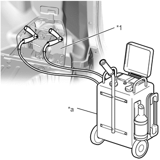
| *1 | Auxiliary Battery |
| *a | Battery Charger |
Connect a charger to the auxiliary battery and put the auxiliary battery into a charging state.
Using the GTS, enter the following menus: Body Electrical / Power Source Control / Utility / Auto Power OFF Cancel
- Body Electrical > Power Source Control > Utility
-
Tester Display Auto Power OFF Cancel - 50005 223 5148
Using the GTS, enter the following menus: Powertrain / EV / Data List / High-Range Hydrogen Pressure (Filtered Value), Medium-Range Hydrogen Pressure (Filtered Value), Tank Area 1 Hydrogen Density, Tank Area 2 Hydrogen Density, Hydrogen Tank 1 Temperature (Filtered Value), Hydrogen Tank 2 Temperature (Filtered Value), Hydrogen Tank 3 Temperature (Filtered Value)
- Powertrain > EV > Data List
-
Tester Display High-Range Hydrogen Pressure (Filtered Value) Medium-Range Hydrogen Pressure (Filtered Value) Tank Area 1 Hydrogen Density Tank Area 2 Hydrogen Density Hydrogen Tank 1 Temperature (Filtered Value) Hydrogen Tank 2 Temperature (Filtered Value) Hydrogen Tank 3 Temperature (Filtered Value) - 50003 397 1030,1031,979,981,1022,1025,1028
- HINT:
-
If the GTS unit setting is absolute pressure (abs), change it to gauge pressure (gauge).
Open the tank shut valves of the No. 1 hydrogen tank assembly, No. 2 hydrogen tank assembly and No. 3 hydrogen tank assembly.
- NOTICE:
-
If the Data List item "Medium-range Hydrogen Pressure (gauge)" decreases to below 0.7 MPa (7.1 kgf/cm2, 102 psi) the tank shut valves of the No. 1 hydrogen tank assembly, No. 2 hydrogen tank assembly and No. 3 hydrogen tank assembly will forcibly close.
If the tank shut valves of the No. 1 hydrogen tank assembly, No. 2 hydrogen tank assembly and No. 3 hydrogen tank assembly do not open, open the tank shut valves again.
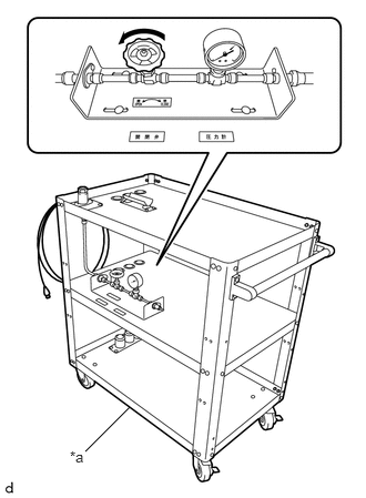
| *a | SST (Venting Stand) |
Open the open/close valve of SST (venting stand), and discharge compressed hydrogen gas.
- SST
- 09404-62010 (09404-06010)
Read the Data List and check that "Hydrogen Tank 1 Temperature (Filter Value)", "Hydrogen Tank 2 Temperature (Filter Value)" and "Hydrogen Tank 3 Temperature (Filter Value)" begin to decrease together.
- HINT:
- ·
By checking that the hydrogen tank temperatures are decreasing, it can be determined that the compressed hydrogen gas is discharging.
·If either one of "Hydrogen Tank 1 Temperature (Filter Value)", "Hydrogen Tank 2 Temperature (Filter Value)" and "Hydrogen Tank 3 Temperature (Filter Value)" does not decrease, perform the following procedure.
(a)Close the open/close valve of SST (venting stand).
- NOTICE:
-
To protect the tank shut valve, make sure to first close the open/close valve of SST (venting stand).
(b)Close the tank shut valves of the No. 1 hydrogen tank assembly, No. 2 hydrogen tank assembly and No. 3 hydrogen tank assembly.
(c)For the side where the hydrogen gas temperature does not decrease, check that the manual valve is open, and if it is closed, open the manual valve.
(d)Open the tank shut valves of the No. 1 hydrogen tank assembly, No. 2 hydrogen tank assembly and No. 3 hydrogen tank assembly.
- NOTICE:
-
If the Data List item "Medium-range Hydrogen Pressure (gauge)" decreases to below 0.7 MPa (7.1 kgf/cm2, 102 psi) the tank shut valves of the No. 1 hydrogen tank assembly, No. 2 hydrogen tank assembly and No. 3 hydrogen tank assembly will forcibly close.
(e)If the tank shut valves of the No. 1 hydrogen tank assembly, No. 2 hydrogen tank assembly and No. 3 hydrogen tank assembly do not open, open the tank shut valves again.
(f)Open the open/close valve of SST (venting stand) again, and discharge the compressed hydrogen gas.
Read the Data List, and if either of the items "Hydrogen Tank 1 Temperature (Filter Value)", "Hydrogen Tank 2 Temperature (Filter Value)" or "Hydrogen Tank 3 Temperature (Filter Value)" have become -30 °C (-86 °F) or less:
Close the open/close valve of SST (venting stand) [*1]
- NOTICE:
-
To protect the tank shut valve, make sure to first close the open/close valve of SST (venting stand).
Close the tank shut valves of the No. 1 hydrogen tank assembly, No. 2 hydrogen tank assembly and No. 3 hydrogen tank assembly.[*2]
Wait until both values "Hydrogen Tank 1 Temperature (Filter Value)", "Hydrogen Tank 2 Temperature (Filter Value)" and "Hydrogen Tank 3 Temperature (Filter Value)" have increased to -20 °C (-68 °F) or more.[*3]
Open the tank shut valves of the No. 1 hydrogen tank assembly, No. 2 hydrogen tank assembly and No. 3 hydrogen tank assembly.[*4]
- NOTICE:
-
If the Data List item "Medium-range Hydrogen Pressure (gauge)" decreases to below 0.7 MPa (7.1 kgf/cm2, 102 psi) the tank shut valves of the No. 1 hydrogen tank assembly, No. 2 hydrogen tank assembly and No. 3 hydrogen tank assembly will forcibly close.
If the tank shut valves of the No. 1 hydrogen tank assembly, No. 2 hydrogen tank assembly and No. 3 hydrogen tank assembly do not open, open the tank shut valves again.[*5]
Open the open/close valve of SST (venting stand) and discharge compressed hydrogen gas again.[*6]
- NOTICE:
-
During the compressed hydrogen gas discharging procedure, if it appears that either "Hydrogen Tank 1 Temperature (Filter Value)", "Hydrogen Tank 2 Temperature (Filter Value)" or "Hydrogen Tank 3 Temperature (Filter Value)" are about to decrease to -30 °C (-86 °F) or less, repeat steps [*1] through [*6].
Continue to monitor the Data List, and when the value of "Medium-range Hydrogen Pressure (gauge)" becomes 0.8 MPa (8.2 kgf/cm2, 116 psi), close the open/close valve of SST (venting stand).
- NOTICE:
- ·
To protect the tank shut valve, make sure to first close the open/close valve of SST (venting stand).
·Forgetting to close the open/close valve of SST (venting stand) and allowing the Data List item "Medium-range Hydrogen Pressure (gauge)" to decrease to below 0.7 MPa (7.1 kgf/cm2, 102 psi) will cause the tank shut valves of the No. 1 hydrogen tank assembly, No. 2 hydrogen tank assembly and No. 3 hydrogen tank assembly to forcibly close.
Read the Data List, and if either of the items "Hydrogen Tank 1 Temperature (Filter Value)", "Hydrogen Tank 2 Temperature (Filter Value)" or "Hydrogen Tank 3 Temperature (Filter Value)" have become -30 °C (-86 °F) or less:
Close the open/close valve of SST (venting stand) [*1]
- NOTICE:
-
To protect the tank shut valve, make sure to first close the open/close valve of SST (venting stand).
Close the tank shut valves of the No. 1 hydrogen tank assembly, No. 2 hydrogen tank assembly and No. 3 hydrogen tank assembly.[*2]
Wait until both values "Hydrogen Tank 1 Temperature (Filter Value)", "Hydrogen Tank 2 Temperature (Filter Value)" and "Hydrogen Tank 3 Temperature (Filter Value)" have increased to -20 °C (-68 °F) or more.[*3]
Open the tank shut valves of the No. 1 hydrogen tank assembly, No. 2 hydrogen tank assembly and No. 3 hydrogen tank assembly.[*4]
- NOTICE:
-
If the Data List item "Medium-range Hydrogen Pressure (gauge)" decreases to below 0.7 MPa (7.1 kgf/cm2, 102 psi) the tank shut valves of the No. 1 hydrogen tank assembly and No. 2 hydrogen tank assembly will forcibly close.
If the tank shut valves of the No. 1 hydrogen tank assembly, No. 2 hydrogen tank assembly and No. 3 hydrogen tank assembly do not open, open the tank shut valves again.[*5]
Open the open/close valve of SST (venting stand) and discharge compressed hydrogen gas again.[*6]
- NOTICE:
-
During the compressed hydrogen gas discharging procedure, if it appears that either "Hydrogen Tank 1 Temperature (Filter Value)" or "Hydrogen Tank 2 Temperature (Filter Value)" are about to decrease to -30 °C (-86 °F) or less, repeat steps [*1] through [*6].
Check that the Data List item "Medium-range Hydrogen Pressure (gauge)" and the pressure on the pressure indicator of SST (venting stand) are less than 0.8 MPa (8.2 kgf/cm2, 116 psi).
- NOTICE:
- ·
The pressure immediately after closing the open/close valve of SST (venting stand) should be less than 0.8 MPa (8.2 kgf/cm2, 116 psi) for both the Data List item "Medium-range Hydrogen Pressure (gauge)" and on the pressure indicator of SST (venting stand).
·If either the Data List item "Medium-range Hydrogen Pressure (gauge)" or the pressure on the pressure indicator of SST (venting stand) are 0.8 MPa (8.2 kgf/cm2, 116 psi) or greater, open the open/close valve of SST (venting stand) and adjust the pressure.
·After the pressure discharging, when the gas temperature inside the hydrogen tank increases, the pressure will also increase, so make sure to continue discharging until the pressure is less than 0.8 MPa (8.2 kgf/cm2, 116 psi).
- HINT:
-
If the pressure immediately after closing the open/close valve of SST (venting stand) is less than 0.8 MPa (8.2 kgf/cm2, 116 psi) for both the Data List item "Medium-range Hydrogen Pressure (gauge)" and on the pressure indicator of SST (venting stand), then the pressurized hydrogen gas discharging procedure is complete.
Close the tank shut valves of both the No. 1 hydrogen tank assembly, No. 2 hydrogen tank assembly and No. 3 hydrogen tank assembly.
Disconnect SST (hydrogen venting tool).
Click hereEngine / Hybrid System>FUEL>FUEL SYSTEM>DISCHARGE COMPRESSED HYDROGEN GAS
10.DISCONNECT SST (HYDROGEN VENTING TOOL)
- CAUTION:
- ·
While discharging pressurized hydrogen gas, the temperature inside the tank decreases and frost may form on the outside. Do not touch tanks, piping, or SST (hydrogen venting tool) when frost has formed on them.
·Touching tanks, piping, or SST (hydrogen venting tool) on which frost has formed could result in burn-like injuries due to frostbite.
| *a | Manual Valve Open |
| *b | Manual Valve Closed |
| *c | Adjustment Bolt |
| *d | Clockwise |
Using an 8 mm hexagon socket wrench, rotate the adjustment bolt clockwise to close the manual valve of the No. 1 hydrogen tank assembly.
- Torque:
- 25 N*m (255 kgf*cm, 18 ft.*lbf)
- NOTICE:
- ·
The manual valve shuts off the pressure from the hydrogen tank assembly, so be careful not to damage the hexagonal portion.
·If the hexagonal portion has been damaged, the No. 1 hydrogen tank assembly must be replaced.
- HINT:
-
If the manual valve is closed at the time of discharging compressed hydrogen gas, this procedure is unnecessary.
| *a | Manual Valve Open |
| *b | Manual Valve Closed |
| *c | Adjustment Bolt |
| *d | Clockwise |
Using an 8 mm hexagon socket wrench, rotate the adjustment bolt clockwise to close the manual valve of the No. 2 hydrogen tank assembly.
- Torque:
- 25 N*m (255 kgf*cm, 18 ft.*lbf)
- NOTICE:
- ·
The manual valve shuts off the pressure from the hydrogen tank assembly, so be careful not to damage the hexagonal portion.
·If the hexagonal portion has been damaged, the No. 2 hydrogen tank assembly must be replaced.
- HINT:
-
If the manual valve is closed at the time of discharging compressed hydrogen gas, this procedure is unnecessary.
| *a | Manual Valve Open |
| *b | Manual Valve Closed |
| *c | Adjustment Bolt |
| *d | Clockwise |
Using an 8 mm hexagon socket wrench, rotate the adjustment bolt clockwise to close the manual valve of the No. 3 hydrogen tank assembly.
- Torque:
- 25 N*m (255 kgf*cm, 18 ft.*lbf)
- NOTICE:
- ·
The manual valve shuts off the pressure from the hydrogen tank assembly, so be careful not to damage the hexagonal portion.
·If the hexagonal portion has been damaged, the No. 3 hydrogen tank assembly must be replaced.
- HINT:
-
If the manual valve is closed at the time of discharging compressed hydrogen gas, this procedure is unnecessary.
| *a | SST (Venting Stand) |
Open the open/close valve of SST (venting stand) and discharge the compressed hydrogen gas remaining inside SST (flexible hose).
- SST
- 09404-62010 (09404-06010)
- NOTICE:
- ·
Do not disconnect SST (flexible hose) while there is still pressure remaining inside it.
·Continue discharging until the pressure gauge of SST (Venting Stand) becomes "0".
Before performing the disconnection procedure, if there are any contaminants such as water droplets adhering near the medium pressure leak check port of the hydrogen supply regulator, wipe them away before performing the procedure.
| *a | SST (Flexible Hose) |
| *b | SST (Venting Stand) |
Disconnect SST (flexible hose) from SST (Venting Stand).
- SST
- 09404-62010 (09404-06010, 09404-06020)
for Type A:
| *a | SST (Flexible Hose) |
Remove SST (flexible hose) from the hydrogen supply regulator.
- SST
- 09404-62010 (09404-06020)
for Type B:
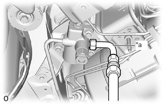
| *a | SST (Flexible Hose) |
Loosen SST (flexible hose).
- SST
- 09404-62010 (09404-06020)
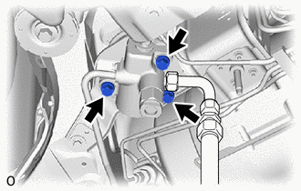
Remove the 3 bolts of the hydrogen supply regulator.
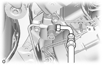
| *a | SST (Flexible Hose) |
Remove SST (flexible hose) from the hydrogen supply regulator.
- SST
- 09404-62010 (09404-06020)
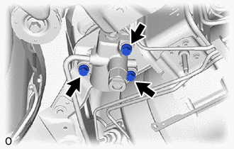
Install the hydrogen supply regulator with the 3 bolts.
- Torque:
- 16.5 N*m (168 kgf*cm, 12 ft.*lbf)
Remove the O-ring from the hydrogen supply regulator.
| *a | Protective Tape |
To prevent damage to the seal portions and threaded portions, and to prevent foreign matter such as dust or metal fragments from entering the openings, cover the seal portions, threaded portions, and openings of the hydrogen supply regulator with protective tape.
To prevent damage to the seal portions and threaded portions, and to prevent foreign matter such as dust or metal fragments from entering the openings, do not remove the protective tape covering the seal portions, threaded portions, and openings of the hydrogen supply regulator until immediately before performing work.
- NOTICE:
-
When frost has formed on the hydrogen tank assembly or piping, water droplets may be formed when the frost begins to melt. If water droplets enter the tank or piping, it could result in blockage of the hydrogen piping, so do not allow water droplets to enter the tank or piping.
Apply TOYOTA Genuine FC Grease to a new O-ring and to the threaded portion of the hydrogen supply regulator.
Install the O-ring to the hydrogen supply regulator.
- NOTICE:
-
During installation, make sure not to damage the O-ring.
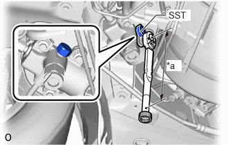
| *a | Specified tightening torque |
Using SST install the No. 1 hydrogen supply regulator plug to the hydrogen supply regulator.
- SST
- 09922-10240
- Torque:
- Specified tightening torque:
9.0 N*m (92 kgf*cm, 80 in.*lbf)
- HINT:
- ·
Calculate the torque wrench reading when changing the fulcrum length of the torque wrench.
Click hereGeneral>INTRODUCTION>REPAIR INSTRUCTION>PRECAUTION
·When using SST (fulcrum length of 40 mm (1.57 in.)) + torque wrench (fulcrum length of 162 mm (6.38 in.)): 7.2 N*m (73 kgf*cm, 64 in.*lbf)
| *a | Manual Valve Closed |
| *b | Manual Valve Open |
| *c | Adjustment Bolt |
| *d | Counterclockwise |
Using an 8 mm socket hexagon wrench, rotate the adjustment bolt counterclockwise, and open the No. 1 hydrogen tank assembly manual valve.
- NOTICE:
- ·
The manual valve shuts off the pressure from the hydrogen tank assembly, so be careful not to damage the hexagonal portion.
·If the hexagonal portion is damaged, it will be impossible to operate the adjustment bolt.
·Do not rotate the adjustment bolt more than 4 rotations.
·Rotating the adjustment bolt more than 4 rotations could damage the manual valve.
·If the manual valve is damaged, it will be necessary to replace the No. 1 hydrogen tank assembly.
- HINT:
-
0.917,1.625 1.094,1.625 1.094,1.625 1.448,1.385 false 0.719,1.531 1.031,1.688 0.313,0.156 10 false *a 3.021,1.271 3.25,1.427 0.229,0.156 10 false *b
*a Adjustment Bolt *b Protrusion
-
When the manual valve is opened, the protrusion of the adjustment bolt is 3.5 mm (0.138 in.) or less.
| *a | Manual Valve Closed |
| *b | Manual Valve Open |
| *c | Adjustment Bolt |
| *d | Counterclockwise |
Using an 8 mm socket hexagon wrench, rotate the adjustment bolt counterclockwise, and open the No. 2 hydrogen tank assembly manual valve.
- NOTICE:
- ·
The manual valve shuts off the pressure from the hydrogen tank assembly, so be careful not to damage the hexagonal portion.
·If the hexagonal portion is damaged, it will be impossible to operate the adjustment bolt.
·Do not rotate the adjustment bolt more than 4 rotations.
·Rotating the adjustment bolt more than 4 rotations could damage the manual valve.
·If the manual valve is damaged, it will be necessary to replace the No. 2 hydrogen tank assembly.
- HINT:
-
0.917,1.625 1.094,1.625 1.094,1.625 1.448,1.385 false 0.719,1.531 1.031,1.688 0.313,0.156 10 false *a 3.021,1.271 3.25,1.427 0.229,0.156 10 false *b
*a Adjustment Bolt *b Protrusion
-
When the manual valve is opened, the protrusion of the adjustment bolt is 3.5 mm (0.138 in.) or less.
| *a | Manual Valve Closed |
| *b | Manual Valve Open |
| *c | Adjustment Bolt |
| *d | Counterclockwise |
Using an 8 mm socket hexagon wrench, rotate the adjustment bolt counterclockwise, and open the No. 3 hydrogen tank assembly manual valve.
- NOTICE:
- ·
The manual valve shuts off the pressure from the hydrogen tank assembly, so be careful not to damage the hexagonal portion.
·If the hexagonal portion is damaged, it will be impossible to operate the adjustment bolt.
·Do not rotate the adjustment bolt more than 4 rotations.
·Rotating the adjustment bolt more than 4 rotations could damage the manual valve.
·If the manual valve is damaged, it will be necessary to replace the No. 3 hydrogen tank assembly.
- HINT:
-
0.917,1.625 1.094,1.625 1.094,1.625 1.448,1.385 false 0.719,1.531 1.031,1.688 0.313,0.156 10 false *a 3.021,1.271 3.25,1.427 0.229,0.156 10 false *b
*a Adjustment Bolt *b Protrusion
-
When the manual valve is opened, the protrusion of the adjustment bolt is 3.5 mm (0.138 in.) or less.
Install the No. 3 FC exhaust pipe.
Click hereEngine / Hybrid System>INTAKE / EXHAUST>EXHAUST PIPE>INSTALLATION
58398F
11.INSTALL NO. 1 FLOOR UNDER COVER
57628E
12.INSTALL REAR FLOOR SIDE MEMBER COVER LH
58402K
13.INSTALL NO. 2 FLOOR BOARD SUB-ASSEMBLY
58403L
14.INSTALL REAR NO. 3 FLOOR BOARD SUB-ASSEMBLY
58404B
15.INSTALL REAR NO. 4 FLOOR BOARD SUB-ASSEMBLY