FC CONTROL FC CONTROL SYSTEM ECU Power Source Circuit
DESCRIPTION
- EV control ECU
-
Refer to description of hybrid control system.
-
Click hereEngine / Hybrid System>HYBRID / BATTERY CONTROL>HYBRID CONTROL SYSTEM>ECU Power Source Circuit
- FC control ECU
-
When the ignition switch is turned to ON, current from the MREL terminal of the EV control ECU flows to the IGCT No. 2 relay and closes the contacts. This causes the current from the auxiliary battery to close the contacts to the FC-B relay, and supplies power to the +B1 and +B2 terminals of the FC control ECU.
- Hydrogen fuel control ECU assembly
-
When the ignition switch is turned to ON, current from the IGSW terminal of the EV control ECU flows to the HF-B relay. This closes the HF-B relay contacts and supplies power to the IGSW terminal of the hydrogen fuel control ECU.
- FC boost control ECU
-
When the ignition switch is turned to ON, current from the MREL terminal of the EV control ECU flows to the IGCT No. 1 relay. This closes the IGCT No. 1 relay contacts and supplies power to the +B1 and +B2 terminals of the FC boost control ECU.
WIRING DIAGRAM
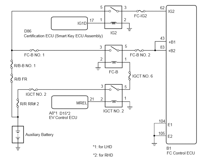
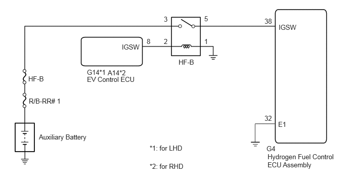
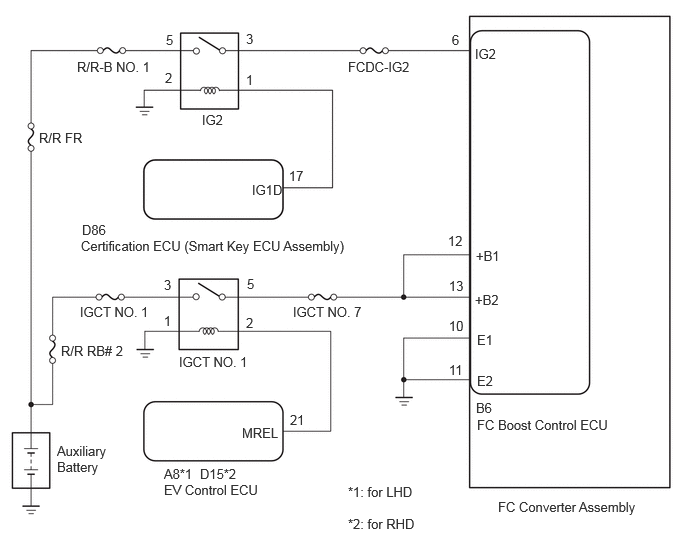
CAUTION / NOTICE / HINT
- CAUTION:
- ·
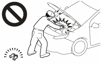
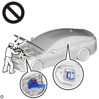
Before the following operations are conducted, take precautions to prevent electric shock by turning the ignition switch off, wearing insulated gloves, and removing the EV supply battery assembly service plug grip and FC converter power outlet cable (inverter with converter assembly) on FC converter side.
Make sure to remove the EV supply battery assembly service plug grip first.
-Inspecting the high-voltage system
-Disconnecting the low voltage connector of the inverter with converter assembly
-Disconnecting the low voltage connector of the EV supply battery assembly
-Disconnecting the low voltage connector of the FC converter assembly
·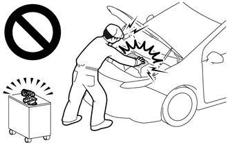
After removing the service plug grip from the EV supply battery assembly, put it in your pocket to prevent other technicians from accidentally reconnecting it while you are working on the high-voltage system. After removing the FC converter power outlet cable (inverter with converter assembly) on FC converter side and use the "HIGH-VOLTAGE, DO NOT TOUCH" sign to notify other technicians that you are working on the high-voltage system.
·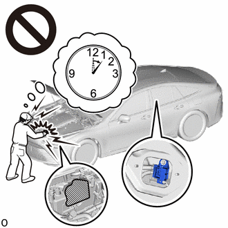
After removal of the EV supply battery assembly service plug grip and FC converter power outlet cable (inverter with converter assembly) on FC converter side, wait for at least 10 minutes before touching the high-voltage connectors and terminals. After waiting for 10 minutes, check the voltage at the terminals in the inspection point in the inverter with converter assembly. The voltage should be 0 V before beginning work.
- HINT:
-
At least 10 minutes are necessary to discharge the high-voltage capacitors inside the inverter with converter assembly and FC stack assembly.
·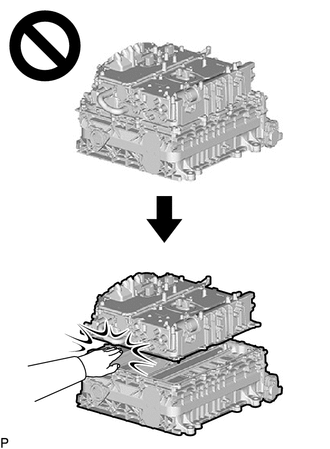
Since high voltage accumulates within the FC stack assembly with FC converter, never perform the work of separating the FC stack assembly with FC converter into the FC converter assembly and FC stack assembly without first performing electrical charge discharge (forced electrical charge discharge or electrical charge self-discharge), because doing so is dangerous.
Click hereEngine / Hybrid System>FC CONTROL>FC STACK>REMOVAL
·Removing and installing the FC stack assembly without first discharging the electrical charge may result in an electric shock due to the high voltage circuit.
- NOTICE:
- ·
Inspect the fuses of circuits related to this system before performing the following procedure.
·This vehicle performs FC system shutdown process after turning the ignition switch off from ON (READY). Therefore, after the ignition switch is turned off from ON (READY), do not perform any work on the electrical system for at least 10 minutes including removing connectors or disconnecting the negative (-) auxiliary battery terminal.
·When the EV control ECU determines that the temperature of FC system components is below 0°C (32°F) when the vehicle is parked with the ignition switch off, it operates the FC air compressor, hydrogen pump and FC cooling water pump for a maximum of 180 seconds to drain the FC stack assembly. When performing inspection or repairs with the ignition switch off (not ON or ON (READY)), disconnect the cable from the negative (-) auxiliary battery terminal before performing work. (If the auxiliary battery voltage is needed to conduct inspection, perform the inspection in an environment with an ambient temperature of 10°C (50°F) or higher.)
PROCEDURE
- Result:
Result Proceed to EV CONTROL ECU A FC CONTROL ECU B HYDROGEN FUEL CONTROL ECU ASSEMBLY C FC BOOST CONTROL ECU D
A
Click hereEngine / Hybrid System>HYBRID / BATTERY CONTROL>HYBRID CONTROL SYSTEM>ECU Power Source Circuit
B
C
D
Disconnect the FC control ECU connector.
Measure the resistance according to the value(s) in the table below.
- Standard Resistance:
Tester Connection Condition Specified Condition Click Location & Routing(B1)Location & Routingewd_type=routing;type=c;code=B1
Click Connector(B1)Engine Compartment>No. 2 Stack Wire>FC Control ECUewd_type=component;type=c;code=B1;pinno=104,105
B1-104 (E1) - Body ground Ignition switch off Below 1 Ω B1-105 (E2) - Body ground Ignition switch off Below 1 Ω
Reconnect the FC control ECU connector.
- Result:
Proceed to OK NG
OK
NG
Disconnect the FC control ECU connector.
Turn the ignition switch to ON.
Measure the voltage according to the value(s) in the table below.
- Standard Voltage:
Tester Connection Condition Specified Condition Click Location & Routing(B1)Location & Routingewd_type=routing;type=c;code=B1
Click Connector(B1)Engine Compartment>No. 2 Stack Wire>FC Control ECUewd_type=component;type=c;code=B1;pinno=43,83
B1-43 (+B1) - Body ground Ignition switch ON 11 to 14 V B1-83 (+B2) - Body ground Ignition switch ON 11 to 14 V
Turn the ignition switch off.
Reconnect the FC control ECU connector.
- Result:
Proceed to OK NG
OK
NG
Disconnect the FC control ECU connector.
Turn the ignition switch to ON.
Measure the voltage according to the value(s) in the table below.
- Standard Voltage:
Tester Connection Condition Specified Condition Click Location & Routing(B1)Location & Routingewd_type=routing;type=c;code=B1
Click Connector(B1)Engine Compartment>No. 2 Stack Wire>FC Control ECUewd_type=component;type=c;code=B1;pinno=62
B1-62 (IG2) - Body ground Ignition switch ON 11 to 14 V
Turn the ignition switch off.
Reconnect the FC control ECU connector.
- Result:
Proceed to OK NG
OK
Click hereGeneral>INTRODUCTION>HOW TO TROUBLESHOOT ECU CONTROLLED SYSTEMS>HOW TO PROCEED WITH TROUBLESHOOTING
NG
OK
NG
Disconnect the FC control ECU connector.
Remove the IG2 relay from the No. 1 front compartment relay block.
Measure the resistance according to the value(s) in the table below.
- Standard Resistance:
Tester Connection Condition Specified Condition Click Location & Routing(B1)Location & Routingewd_type=routing;type=c;code=B1
Click Connector(B1)Engine Compartment>No. 2 Stack Wire>FC Control ECUewd_type=component;type=c;code=B1;pinno=62
B1-62 (IG2) - 3 (IG2 relay holder) Ignition switch off Below 1 Ω B1-62 (IG2) or 3 (IG2 relay holder) - Body ground and other terminals Ignition switch off 10 kΩ or higher
Reconnect the FC control ECU connector.
Reinstall the IG2 relay.
- Result:
Proceed to OK NG
OK
NG
OK
NG
Remove the FC-B relay from the No. 1 front compartment relay block.
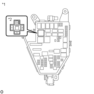
| *1 | No. 1 Front Compartment Relay Block |
| *2 | FC-B Relay Holder |
Measure the voltage according to the value(s) in the table below.
- Standard Voltage:
Tester Connection Condition Specified Condition 3 (FC-B relay holder) - Body ground Ignition switch off 11 to 14 V
Reinstall the FC-B relay.
- Result:
Proceed to OK NG
OK
NG
Remove the FC-B relay from the No. 1 front compartment relay block.
Measure the resistance according to the value(s) in the table below.
- Standard Resistance:
Tester Connection Condition Specified Condition 2 (FC-B relay holder) - Body ground Always Below 1 Ω
Reinstall the FC-B relay.
- Result:
Proceed to OK NG
OK
NG
Remove the FC-B relay from the No. 1 front compartment relay block.
Remove the IGCT NO. 1 relay and IGCT NO. 2 relay from the luggage room relay block.
- HINT:
-
Remove the IGCT NO. 2 relay connected between the checked terminals as the coil inside the relay influences the measurement value.
Measure the resistance according to the value(s) in the table below.
- Standard Resistance:
Tester Connection Condition Specified Condition 1 (FC-B relay holder) - 5 (IGCT NO. 2 relay holder) Always Below 1 Ω 1 (FC-B NO. 1 relay holder) or 5 (IGCT NO. 2 relay holder) - Body ground and other terminals Always 10 kΩ or higher
Reinstall the FC-B relay.
Reinstall the IGCT NO. 1 relay and IGCT NO. 2 relay.
- Result:
Proceed to OK NG
OK
NG
Click hereEngine / Hybrid System>HYBRID / BATTERY CONTROL>RELAY>ON-VEHICLE INSPECTION
- Result:
Proceed to OK NG
OK
NG
Remove the IGCT NO. 2 relay from the luggage room relay block.
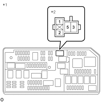
| *1 | Luggage Room Relay Block. |
| *2 | IGCT NO. 2 Relay Holder |
Measure the voltage according to the value(s) in the table below.
- Standard Voltage:
Tester Connection Condition Specified Condition 3 (IGCT NO. 2 relay holder) - Body ground Ignition switch off 11 to 14 V
Reinstall the IGCT NO. 2 relay.
- Result:
Proceed to OK NG
OK
NG
Remove the IGCT NO. 2 relay from the luggage room relay block.
Measure the resistance according to the value(s) in the table below.
- Standard Resistance:
Tester Connection Condition Specified Condition 2 (IGCT NO. 2 relay holder) - Body ground Always Below 1 Ω
Reinstall the IGCT NO. 2 relay.
- Result:
Proceed to OK NG
OK
NG
Disconnect the EV control ECU connector.
Remove the IGCT NO. 1 relay and IGCT NO. 2 relay from the luggage room relay block.
- HINT:
-
Remove the IGCT NO. 2 relay connected between the checked terminals as the coil inside the relay influences the measurement value.
Measure the resistance according to the value(s) in the table below.
- Standard Resistance (for LHD):
Tester Connection Condition Specified Condition Click Location & Routing(A8)Location & Routingewd_type=routing;type=c;code=A8
Click Connector(A8)Instrument Panel>Front Compartment Main Wire>EV Control ECUewd_type=component;type=c;code=A8;pinno=21
A8-21 (MREL) - 1 (IGCT NO. 2 relay holder) Always Below 1 Ω A8-21 (MREL) or 1 (IGCT NO. 2 relay holder) - Body ground and other terminals Always 10 kΩ or higher
- Standard Resistance (for RHD):
Tester Connection Condition Specified Condition Click Location & Routing(D15)Location & Routingewd_type=routing;type=c;code=D15
Click Connector(D15)Instrument Panel>Instrument Panel Wire>EV Control ECUewd_type=component;type=c;code=D15;pinno=21
D15-21 (MREL) - 1 (IGCT NO. 2 relay holder) Always Below 1 Ω D15-21 (MREL) or 1 (IGCT NO. 2 relay holder) - Body ground and other terminals Always Below 1 Ω
- Result:
Proceed to OK NG
Reinstall the IGCT NO. 1 relay and IGCT NO. 2 relay.
Reconnect the EV control ECU connector.
OK
Click hereEngine / Hybrid System>HYBRID / BATTERY CONTROL>HYBRID CONTROL SYSTEM>ECU Power Source Circuit
NG
Disconnect the hydrogen fuel control ECU assembly connector.
Measure the resistance according to the value(s) in the table below.
- Standard Resistance:
Tester Connection Condition Specified Condition Click Location & Routing(G4)Location & Routingewd_type=routing;type=c;code=G4
Click Connector(G4)Body>Floor Wire / No. 3 Floor Wire>Hydrogen Fuel Control ECU Assemblyewd_type=component;type=c;code=G4;pinno=32
G4-32 (E1) - Body ground Ignition switch off Below 1 Ω
Reconnect the hydrogen fuel control ECU assembly connector.
- Result:
Proceed to OK NG
OK
NG
Disconnect the hydrogen fuel control ECU assembly connector.
Turn the ignition switch to ON.
Measure the voltage according to the value(s) in the table below.
- Standard Voltage:
Tester Connection Condition Specified Condition Click Location & Routing(G4)Location & Routingewd_type=routing;type=c;code=G4
Click Connector(G4)Body>Floor Wire / No. 3 Floor Wire>Hydrogen Fuel Control ECU Assemblyewd_type=component;type=c;code=G4;pinno=38
G4-38 (IGSW - Body ground Ignition switch ON 11 to 14 V
Turn the ignition switch off.
Reconnect the hydrogen fuel control ECU assembly connector.
- Result:
Proceed to OK NG
OK
Click hereGeneral>INTRODUCTION>HOW TO TROUBLESHOOT ECU CONTROLLED SYSTEMS>HOW TO PROCEED WITH TROUBLESHOOTING
NG
OK
NG
Disconnect the hydrogen fuel control ECU assembly connector.
Remove the HF-B relay from the luggage room relay block.
Measure the resistance according to the value(s) in the table below.
- Standard Resistance:
Tester Connection Condition Specified Condition Click Location & Routing(G4)Location & Routingewd_type=routing;type=c;code=G4
Click Connector(G4)Body>Floor Wire / No. 3 Floor Wire>Hydrogen Fuel Control ECU Assemblyewd_type=component;type=c;code=G4;pinno=38
G4-38 (IGSW) - 5 (HF-B relay holder) Ignition switch off Below 1 Ω G4-38 (IGSW) or 5 (HF-B relay holder) - Body ground and other terminals Ignition switch off 10 kΩ or higher
Reconnect the hydrogen fuel control ECU assembly connector.
Reinstall the HF-B relay.
- Result:
Proceed to OK NG
OK
NG
Remove the HF-B relay from the luggage room relay block.
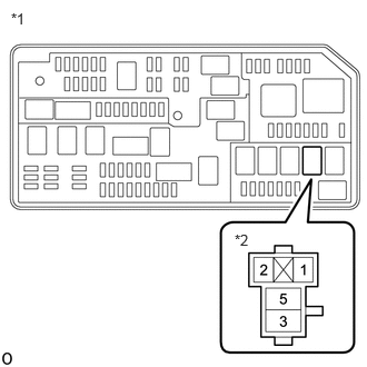
| *1 | Luggage Room Relay Block. |
| *2 | HF-B Relay Holder |
Measure the voltage according to the value(s) in the table below.
- Standard Voltage:
Tester Connection Condition Specified Condition 3 (HF-B relay holder) - Body ground Ignition switch off 11 to 14 V
Reinstall the HF-B relay.
- Result:
Proceed to OK NG
OK
NG
Remove the HF-B relay from the luggage room relay block.
Measure the resistance according to the value(s) in the table below.
- Standard Resistance:
Tester Connection Condition Specified Condition 1 (HF-B relay holder) - Body ground Always Below 1 Ω
Reinstall the HF-B relay.
- Result:
Proceed to OK NG
OK
NG
Disconnect the EV control ECU connector.
Remove the HF-B relay from the luggage room relay block.
Measure the resistance according to the value(s) in the table below.
- Standard Resistance (for LHD):
Tester Connection Condition Specified Condition Click Location & Routing(G14)Location & Routingewd_type=routing;type=c;code=G14
Click Connector(G14)Instrument Panel>Floor Wire>EV Control ECUewd_type=component;type=c;code=G14;pinno=8
G14-8 (IGSW) - 2 (HF-B relay holder) Always Below 1 Ω G14-8 (IGSW) or 2 (HF-B relay holder) - Body ground and other terminals Always 10 kΩ or higher
- Standard Resistance (for RHD):
Tester Connection Condition Specified Condition Click Location & Routing(A14)Location & Routingewd_type=routing;type=c;code=A14
Click Connector(A14)Instrument Panel>Front Compartment Main Wire>EV Control ECUewd_type=component;type=c;code=A14;pinno=8
A14-8 (IGSW) - 2 (HF-B relay holder) Always Below 1 Ω A14-8 (IGSW) or 2 (HF-B relay holder) - Body ground and other terminals Always 10 kΩ or higher
- Result:
Proceed to OK NG
Reinstall the HF-B relay.
Reconnect the EV control ECU connector.
OK
Click hereEngine / Hybrid System>HYBRID / BATTERY CONTROL>HYBRID CONTROL SYSTEM>ECU Power Source Circuit
NG
- CAUTION:
-
Be sure to wear insulated gloves.
Check that the service plug grip is not installed to EV supply battery assembly and the FC converter power outlet cable (inverter with converter assembly) is not connected to the FC converter assembly.
- NOTICE:
-
After removing the EV supply battery assembly service plug grip and FC converter power outlet cable (inverter with converter assembly) on FC converter side, do not turn the ignition switch to ON (READY), unless instructed by the repair manual because this may cause a malfunction.
Remove the electric heater sub-assembly.
Disconnect the FC boost control ECU (FC converter assembly) connector.
Measure the resistance according to the value(s) in the table below.
- Standard Resistance:
Tester Connection Condition Specified Condition Click Location & Routing(B6)Location & Routingewd_type=routing;type=c;code=B6
Click Connector(B6)Engine Compartment>No. 2 Stack Wire>FC Converter Assemblyewd_type=component;type=c;code=B6;pinno=10,11
B6-10 (E1) - Body ground Ignition switch off Below 1 Ω B6-11 (E2) - Body ground Ignition switch off Below 1 Ω
Reconnect the FC boost control ECU (FC converter assembly) connector.
Install the electric heater sub-assembly.
- Result:
Proceed to OK NG
OK
NG
- CAUTION:
-
Be sure to wear insulated gloves.
Check that the service plug grip is not installed to EV supply battery assembly and the FC converter power outlet cable (inverter with converter assembly) is not connected to the FC converter assembly.
- NOTICE:
-
After removing the EV supply battery assembly service plug grip and FC converter power outlet cable (inverter with converter assembly) on FC converter side, do not turn the ignition switch to ON (READY), unless instructed by the repair manual because this may cause a malfunction.
Remove the electric heater sub-assembly.
Disconnect the FC boost control ECU (FC converter assembly) connector.
Connect the cable to the negative (-) auxiliary battery terminal.
Turn the ignition switch to ON.
Measure the voltage according to the value(s) in the table below.
- Standard Voltage:
Tester Connection Condition Specified Condition Click Location & Routing(B6)Location & Routingewd_type=routing;type=c;code=B6
Click Connector(B6)Engine Compartment>No. 2 Stack Wire>FC Converter Assemblyewd_type=component;type=c;code=B6;pinno=12,13
B6-12 (+B1) - Body ground Ignition switch ON 11 to 15.5 V B6-13 (+B2) - Body ground Ignition switch ON 11 to 15.5 V
Turn the ignition switch off.
Disconnect the cable from the negative (-) auxiliary battery terminal.
Reconnect the FC boost control ECU (FC converter assembly) connector.
Install the electric heater sub-assembly.
- Result:
Proceed to OK NG
OK
NG
- CAUTION:
-
Be sure to wear insulated gloves.
Check that the service plug grip is not installed to EV supply battery assembly and the FC converter power outlet cable (inverter with converter assembly) is not connected to the FC converter assembly.
- NOTICE:
-
After removing the EV supply battery assembly service plug grip and FC converter power outlet cable (inverter with converter assembly) on FC converter side, do not turn the ignition switch to ON (READY), unless instructed by the repair manual because this may cause a malfunction.
Remove the electric heater sub-assembly.
Disconnect the FC boost control ECU (FC converter assembly) connector.
Connect the cable to the negative (-) auxiliary battery terminal.
Turn the ignition switch to ON.
Measure the voltage according to the value(s) in the table below.
- Standard Voltage:
Tester Connection Condition Specified Condition Click Location & Routing(B6)Location & Routingewd_type=routing;type=c;code=B6
Click Connector(B6)Engine Compartment>No. 2 Stack Wire>FC Converter Assemblyewd_type=component;type=c;code=B6;pinno=6
B6-6 (IG2) - Body ground Ignition switch ON 11 to 15.5 V
Turn the ignition switch off.
Disconnect the cable from the negative (-) auxiliary battery terminal.
Reconnect the FC boost control ECU (FC converter assembly) connector.
Install the electric heater sub-assembly.
- Result:
Proceed to OK NG
OK
Click hereGeneral>INTRODUCTION>HOW TO TROUBLESHOOT ECU CONTROLLED SYSTEMS>HOW TO PROCEED WITH TROUBLESHOOTING
NG
OK
NG
- CAUTION:
-
Be sure to wear insulated gloves.
Check that the service plug grip is not installed to EV supply battery assembly and the FC converter power outlet cable (inverter with converter assembly) is not connected to the FC converter assembly.
- NOTICE:
-
After removing the EV supply battery assembly service plug grip and FC converter power outlet cable (inverter with converter assembly) on FC converter side, do not turn the ignition switch to ON (READY), unless instructed by the repair manual because this may cause a malfunction.
Remove the electric heater sub-assembly.
Disconnect the FC boost control ECU (FC converter assembly) connector.
Remove the IG2 relay from the No. 1 front compartment relay block.
Measure the resistance according to the value(s) in the table below.
- Standard Resistance:
Tester Connection Condition Specified Condition Click Location & Routing(B6)Location & Routingewd_type=routing;type=c;code=B6
Click Connector(B6)Engine Compartment>No. 2 Stack Wire>FC Converter Assemblyewd_type=component;type=c;code=B6;pinno=6
B6-6 (IG2) - 3 (IG2 relay holder) Ignition switch off Below 1 Ω B6-6 (IG2) or 3 (IG2 relay holder) - Body ground and other terminals Ignition switch off 10 kΩ or higher
Reconnect the FC boost control ECU (FC converter assembly) connector.
Install the electric heater sub-assembly.
- Result:
Proceed to OK NG
OK
NG
Remove the IG2 relay from the No. 1 front compartment relay block.
| *1 | No. 1 Front Compartment Relay Block |
| *2 | IG2 Relay Holder |
Measure the voltage according to the value(s) in the table below.
- Standard Voltage:
Tester Connection Condition Specified Condition 3 (IG2 relay holder) - Body ground Ignition switch off 11 to 14 V
Reinstall the IG2 relay.
- Result:
Proceed to OK NG
OK
NG
Remove the IG2 relay from the No. 1 front compartment relay block.
Measure the resistance according to the value(s) in the table below.
- Standard Resistance:
Tester Connection Condition Specified Condition 1 (IG2 relay holder) - Body ground Always Below 1 Ω
Reinstall the IG2 relay.
- Result:
Proceed to OK NG
OK
NG
Disconnect the certification ECU (smart key ECU assembly) connector.
Remove the IG1 relay and IG2 relay from the No. 1 front compartment relay block.
- HINT:
-
Remove the IG1 relay connected between the checked terminals as the coil inside the relay influences the measurement value.
Disconnect the 4A, 4D and 4H driver side junction block connectors. (for LHD only)
- HINT:
-
Remove the passenger side junction block internal relay connected between the checked terminals as the coil inside the relay influences the measurement value.
Disconnect the 5A, 5D and 5H passenger side junction block connectors. (for RHD only)
- HINT:
-
Remove the passenger side junction block internal relay connected between the checked terminals as the coil inside the relay influences the measurement value.
Measure the resistance according to the value(s) in the table below.
- Standard Resistance:
Tester Connection Condition Specified Condition Click Location & Routing(D86)Location & Routingewd_type=routing;type=c;code=D86
Click Connector(D86)Instrument Panel>Instrument Panel Wire>Certification ECUewd_type=component;type=c;code=D86;pinno=17
D86-17 (IG1D) - 2 (IG2 relay holder) Always Below 1 Ω D86-17 (IG1D) or 2 (IG2 relay holder) - Body ground and other terminals Always 10 kΩ or higher
- Result:
Proceed to OK NG
Reconnect the passenger side junction block connector. (for RHD only)
Reconnect the driver side junction block connector. (for LHD only)
Reinstall the IG1 relay and IG2 relay.
Reconnect the certification ECU (smart key ECU assembly) connector.
OK
NG
Click hereEngine / Hybrid System>HYBRID / BATTERY CONTROL>RELAY>ON-VEHICLE INSPECTION
- Result:
Proceed to OK NG
OK
NG
- CAUTION:
-
Be sure to wear insulated gloves.
Check that the service plug grip is not installed to EV supply battery assembly and the FC converter power outlet cable (inverter with converter assembly) is not connected to the FC converter assembly.
- NOTICE:
-
After removing the EV supply battery assembly service plug grip and FC converter power outlet cable (inverter with converter assembly) on FC converter side, do not turn the ignition switch to ON (READY), unless instructed by the repair manual because this may cause a malfunction.
Remove the electric heater sub-assembly.
Disconnect the FC boost control ECU (FC converter assembly) connector.
Remove the IGCT NO. 1 relay from the luggage room relay block.
Measure the resistance according to the value(s) in the table below.
- Standard Resistance:
Tester Connection Condition Specified Condition Click Location & Routing(B6)Location & Routingewd_type=routing;type=c;code=B6
Click Connector(B6)Engine Compartment>No. 2 Stack Wire>FC Converter Assemblyewd_type=component;type=c;code=B6;pinno=12,13
B6-12 (+B1) - 5 (IGCT NO. 1 relay holder) Ignition switch off Below 1 Ω B6-13 (+B2) - 5 (IGCT NO. 1 relay holder) Ignition switch off Below 1 Ω B6-12 (+B1), B6-13 (+B2) or 5 (IGCT NO. 2 relay holder) - Body ground and other terminals Ignition switch off 10 kΩ or higher
Reinstall the IGCT NO. 1 relay.
Reconnect the FC boost control ECU (FC converter assembly) connector.
Install the electric heater sub-assembly.
- Result:
Proceed to OK NG
OK
NG
Remove the IGCT NO. 1 relay from the luggage room relay block.
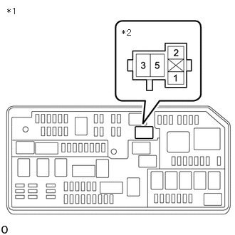
| *1 | Luggage Room Relay Block. |
| *2 | IGCT NO. 1 Relay Holder |
Measure the voltage according to the value(s) in the table below.
- Standard Voltage:
Tester Connection Condition Specified Condition 3 (IGCT NO. 1 relay holder) - Body ground Ignition switch off 11 to 14 V
Reinstall the IGCT NO. 1 relay.
- Result:
Proceed to OK NG
OK
NG
Remove the IGCT NO. 1 relay from the luggage room relay block.
Measure the resistance according to the value(s) in the table below.
- Standard Resistance:
Tester Connection Condition Specified Condition 1 (IGCT NO. 1 relay holder) - Body ground Always Below 1 Ω
Reinstall the IGCT NO. 1 relay.
- Result:
Proceed to OK NG
OK
NG
Disconnect the EV control ECU connector.
Remove the IGCT NO. 1 relay and IGCT NO. 2 relay from the luggage room relay block.
- HINT:
-
Remove the IGCT NO. 2 relay connected between the checked terminals as the coil inside the relay influences the measurement value.
Measure the resistance according to the value(s) in the table below.
- Standard Resistance (for LHD):
Tester Connection Condition Specified Condition Click Location & Routing(A8)Location & Routingewd_type=routing;type=c;code=A8
Click Connector(A8)Instrument Panel>Front Compartment Main Wire>EV Control ECUewd_type=component;type=c;code=A8;pinno=21
A8-21 (MREL) - 2 (IGCT NO. 1 relay holder) Always Below 1 Ω A8-21 (MREL) or 2 (IGCT NO. 1 relay holder) - Body ground and other terminals Always 10 kΩ or higher
- Standard Resistance (for RHD):
Tester Connection Condition Specified Condition Click Location & Routing(D15)Location & Routingewd_type=routing;type=c;code=D15
Click Connector(D15)Instrument Panel>Instrument Panel Wire>EV Control ECUewd_type=component;type=c;code=D15;pinno=21
D15-21 (MREL) - 2 (IGCT NO. 1 relay holder) Always Below 1 Ω D15-21 (MREL) or 2 (IGCT NO. 1 relay holder) - Body ground and other terminals Always 10 kΩ or higher
- Result:
Proceed to OK NG
Reinstall the IGCT NO. 1 relay and IGCT NO. 2 relay.
Reconnect the EV control ECU connector.
OK
Click hereEngine / Hybrid System>HYBRID / BATTERY CONTROL>HYBRID CONTROL SYSTEM>ECU Power Source Circuit
NG