FC CONTROL FC CONTROL SYSTEM Cooling System
DESCRIPTION
The cause of the malfunction may be the cooling system.
Check whether the grille is blocked, whether coolant is leaking, the EV radiator fan operating condition and whether EV coolant has frozen.
| Area | Inspection | Step |
|---|---|---|
| Grille blockage, coolant amount, coolant hoses, EV radiator fan | Check for overheating due to EV cooling system malfunction | 1, 2, 3, 4 |
| Coolant freezing check | Check freeze frame values to determine whether the EV coolant was frozen when the DTC was stored | 5 |
SYSTEM DESCRIPTION
Refer to cooling system for hybrid control system.
Click hereEngine / Hybrid System>HYBRID / BATTERY CONTROL>HYBRID CONTROL SYSTEM>Cooling System
CAUTION / NOTICE / HINT
This step is referenced from the procedures for each DTC.
If the inspection results below are normal, perform the next procedure for the referenced DTC.
- CAUTION:
- ·
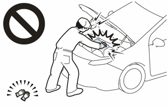
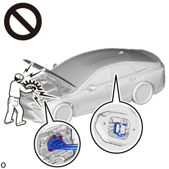
Before the following operations are conducted, take precautions to prevent electric shock by turning the ignition switch off, wearing insulated gloves, and removing the EV supply battery assembly service plug grip and FC converter power outlet cable (inverter with converter assembly) on FC converter side.
Make sure to remove the EV supply battery assembly service plug grip first.
-Inspecting the high-voltage system
-Disconnecting the low voltage connector of the inverter with converter assembly
-Disconnecting the low voltage connector of the EV supply battery assembly
-Disconnecting the low voltage connector of the FC converter assembly
·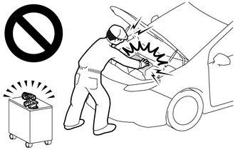
After removing the service plug grip from the EV supply battery assembly, put it in your pocket to prevent other technicians from accidentally reconnecting it while you are working on the high-voltage system. After removing the FC converter power outlet cable (inverter with converter assembly) on FC converter side and use the "HIGH-VOLTAGE, DO NOT TOUCH" sign to notify other technicians that you are working on the high-voltage system.
·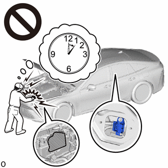
After removal of the EV supply battery assembly service plug grip and FC converter power outlet cable (inverter with converter assembly) on FC converter side, wait for at least 10 minutes before touching the high-voltage connectors and terminals. After waiting for 10 minutes, check the voltage at the terminals in the inspection point in the inverter with converter assembly. The voltage should be 0 V before beginning work.
- HINT:
-
At least 10 minutes are necessary to discharge the high-voltage capacitors inside the inverter with converter assembly and FC stack assembly.
·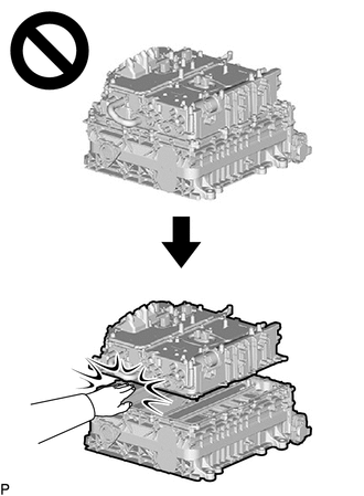
Since high voltage accumulates within the FC stack assembly with FC converter, never perform the work of separating the FC stack assembly with FC converter into the FC converter assembly and FC stack assembly without first performing electrical charge discharge (forced electrical charge discharge or electrical charge self-discharge), because doing so is dangerous.
Click hereEngine / Hybrid System>FC CONTROL>FC STACK>REMOVAL
·Removing and installing the FC stack assembly without first discharging the electrical charge may result in an electric shock due to the high voltage circuit.
- NOTICE:
- ·
When reinstalling the service plug grip to the EV supply battery assembly, after lowering the EV supply battery assembly service plug grip 90°, securely slide it until a "click" sound is heard.
Click hereEngine / Hybrid System>FC CONTROL>FC CONTROL SYSTEM>PRECAUTION
·This vehicle performs FC system shutdown process after turning the ignition switch off from ON (READY). Therefore, after the ignition switch is turned off from ON (READY), do not perform any work on the electrical system for at least 10 minutes including removing connectors or disconnecting the negative (-) auxiliary battery terminal.
·When the EV control ECU determines that the temperature of FC system components is below 0°C (32°F) when the vehicle is parked with the ignition switch off, it operates the FC air compressor, hydrogen pump and FC cooling water pump for a maximum of 180 seconds to drain the FC stack assembly. When performing inspection or repairs with the ignition switch off (not ON or ON (READY)), disconnect the cable from the negative (-) auxiliary battery terminal before performing work. (If the auxiliary battery voltage is needed to conduct inspection, perform the inspection in an environment with an ambient temperature of 10°C (50°F) or higher.)
PROCEDURE
Make sure that the front side of the radiator grille is not blocked with anything.
Ask the customer if the front side of the radiator grille was blocked with anything.
- Result:
Result Proceed to Not blocked A Is/was blocked B
- HINT:
-
If the radiator grille is blocked, the inverter coolant temperature will increase and this DTC may be stored.
A
B
Check that the inverter reserve tank assembly contains coolant at the Low level or higher.
Check for EV coolant leaks.
- Result:
Result Proceed to No leaks are found and the EV coolant level in the inverter reserve tank assembly is above the low line A No leaks are found and the EV coolant level in the inverter reserve tank assembly is below the low line B EV coolant leaks are evident C
- HINT:
- ·
After repairing the EV coolant leaks and adding coolant, perform the "Activate the Water Pump" and the "Radiator Fan1" Active Test (EV Active Test item) and make sure that there are no malfunctions.
·The EV water pump with motor assembly has a protection circuit function in case of water leakage, so it does not need to be replaced unless the cause of the water leak is the EV water pump with motor assembly itself.
A
B
C
Check that the cooling system hoses are not kinked or clogged.
- OK:
The cooling system hoses are not kinked or clogged.
- Result:
Proceed to OK NG
OK
NG
Perform the Active Test.
- Powertrain > EV > Active Test
-
Active Test Display Control the Radiator Fan 1 -
Data List Display Radiator Fan 1 Drive Voltage - 50004 397 18 705
- OK:
The cooling fan rotates.
- Result:
Proceed to OK NG
Turn the ignition switch off.
OK
NG
Read the freeze frame data item "Ambient Temperature" using the GTS.
- Powertrain > EV > Trouble Codes
- 50001 397
Check if the freeze frame data item "Ambient Temperature" is below the freezing temperature of the HV coolant.
- Result:
Result Proceed to Ambient Temperature value is above freezing temperature of the EV coolant A Ambient Temperature value is below freezing temperature of the EV coolant B
- HINT:
- ·
EV coolant (SLLC) with a 30% concentration freezes at -15°C (5°F) and EV coolant with a 50% concentration freezes at -35°C (-31°F).
·If the EV coolant freezes, the EV coolant will not be able to circulate, so the coolant temperature inside the FC converter assembly will increase, which may result in DTC output.
·A DTC is stored when the EV water pump with motor assembly impeller cannot rotate due to freezing of the HV coolant.
·If DTCs are output due to freezing of the EV coolant, the problem symptom cannot be reproduced. Check the EV coolant replacement history and whether the EV coolant was frozen based on the ambient temperature when the DTCs were stored.
Turn the ignition switch off.
A
B