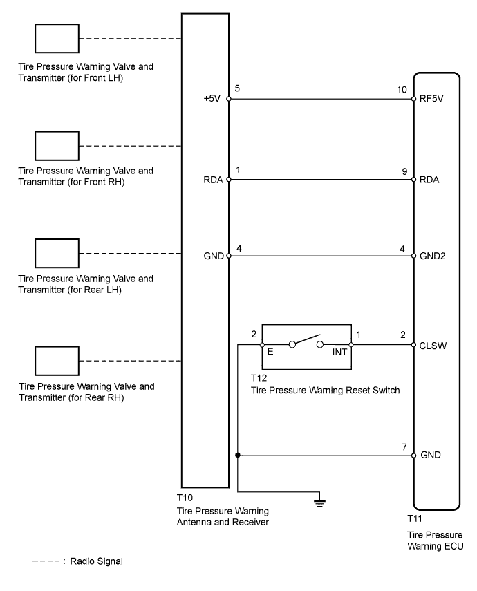
DTC C2121/21 No Signal from Transmitter ID1 in Main Mode |
DTC C2122/22 No Signal from Transmitter ID2 in Main Mode |
DTC C2123/23 No Signal from Transmitter ID3 in Main Mode |
DTC C2124/24 No Signal from Transmitter ID4 in Main Mode |
DTC C2181/81 Transmitter ID1 not Received (Test Mode DTC) |
DTC C2182/82 Transmitter ID2 not Received (Test Mode DTC) |
DTC C2183/83 Transmitter ID3 not Received (Test Mode DTC) |
DTC C2184/84 Transmitter ID4 not Received (Test Mode DTC) |
| DTC Code | DTC Detection Condition | Trouble Area |
| C2121/21 C2122/22 C2123/23 C2124/24 | When all conditions below are met:
|
|
| C2181/81 C2182/82 C2183/83 C2184/84 | Test mode procedure is performed. |
|
| 1.CHECK FREQUENCY RECEIVING CONDITION |
Check if the vehicle is located in areas such as the ones described below:
Facilities or devices that use similar radio frequencies are located in the vicinity of the vehicle.
Devices using similar radio frequencies are used in the vehicle.
|
| ||||
| OK | |
 |
| 2.IDENTIFY TRANSMITTER CORRESPONDING TO DTC |
Set the tire pressure to the appropriate specified values (Click here).
Turn the power switch off.
Connect the Techstream to the DLC3.
Turn the power switch on (IG) and turn the Techstream on.
Enter the following menus: Chassis / Tire Pressure Monitor / Data List.
Check the values by referring to the table below.
| Tester Display | Measurement Item/Range | Normal Condition | Diagnostic Note |
| ID1 Tire Inflation Pressure | ID1 tire inflation pressure / min.: Absolute pressure / 0 kPa (0 kgf/cm2, 0 psi), Relative pressure / -100 kPa (-1 kgf/cm2, -14 psi) max.: Absolute pressure / 637.5 kPa (6.5 kgf/cm2, 92 psi), Relative pressure / 537.5 kPa (5.4 kgf/cm2, 78 psi) | Actual tire inflation pressure | If 0 kPa (0 kgf/cm2, 0 psi) is displayed for absolute pressure or -100 kPa (-1 kgf/cm2, -14 psi) is displayed for relative pressure, data has not been received.* |
| ID2 Tire Inflation Pressure | ID2 tire inflation pressure / min.: Absolute pressure / 0 kPa (0 kgf/cm2, 0 psi), Relative pressure / -100 kPa (-1 kgf/cm2, -14 psi) max.: Absolute pressure / 637.5 kPa (6.5 kgf/cm2, 92 psi), Relative pressure / 537.5 kPa (5.4 kgf/cm2, 78 psi) | Actual tire inflation pressure | If 0 kPa (0 kgf/cm2, 0 psi) is displayed for absolute pressure or -100 kPa (-1 kgf/cm2, -14 psi) is displayed for relative pressure, data has not been received.* |
| ID3 Tire Inflation Pressure | ID3 tire inflation pressure / min.: Absolute pressure / 0 kPa (0 kgf/cm2, 0 psi), Relative pressure / -100 kPa (-1 kgf/cm2, -14 psi) max.: Absolute pressure / 637.5 kPa (6.5 kgf/cm2, 92 psi), Relative pressure / 537.5 kPa (5.4 kgf/cm2, 78 psi) | Actual tire inflation pressure | If 0 kPa (0 kgf/cm2, 0 psi) is displayed for absolute pressure or -100 kPa (-1 kgf/cm2, -14 psi) is displayed for relative pressure, data has not been received.* |
| ID4 Tire Inflation Pressure | ID4 tire inflation pressure / min.: Absolute pressure / 0 kPa (0 kgf/cm2, 0 psi), Relative pressure / -100 kPa (-1 kgf/cm2, -14 psi) max.: Absolute pressure / 637.5 kPa (6.5 kgf/cm2, 92 psi), Relative pressure / 537.5 kPa (5.4 kgf/cm2, 78 psi) | Actual tire inflation pressure | If 0 kPa (0 kgf/cm2, 0 psi) is displayed for absolute pressure or -100 kPa (-1 kgf/cm2, -14 psi) is displayed for relative pressure, data has not been received.* |
Rapidly reduce the tire pressure for each wheel at least 40 kPa (0.4 kgf/cm2, 5.8 psi) within 30 seconds.
Check the DATA LIST.
After confirming that the "ID Tire Inflation Pressure" data for one tire (ID1 to ID4) has changed, repeat this procedure one by one. Identify the transmitter that corresponds to the DTC.
| Condition | Proceed to |
| All abnormal | A |
| One or more of transmitters abnormal | B |
| All normal | C |
|
| ||||
|
| ||||
| A | |
|
| 3.CHECK HARNESS AND CONNECTOR (ECU - RECEIVER) |
Disconnect the T11 ECU connector.
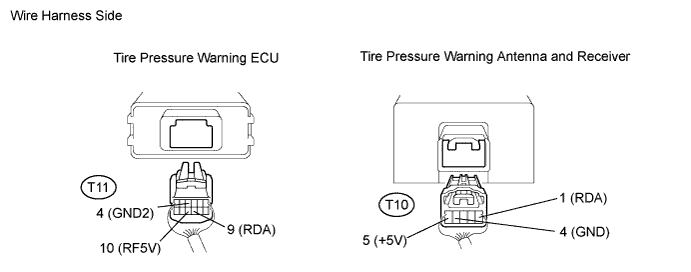
Disconnect the T10 receiver connector.
Measure the resistance according to the value(s) in the table below.
| Tester Connection | Condition | Specified Condition |
| T11-9 (RDA) - T10-1 (RDA) | Always | Below 1 Ω |
| T11-4 (GND2) - T10-4 (GND) | Always | Below 1 Ω |
| T11-10 (RF5V) - T10-5 (+5V) | Always | Below 1 Ω |
| T11-9 (RDA) or T10-1 (RDA) - Body ground | Always | 10 kΩ or higher |
| T11-4 (GND2) or T10-4 (GND) - Body ground | Always | 10 kΩ or higher |
| T11-10 (RF5V) or T10-5 (+5V) - Body ground | Always | 10 kΩ or higher |
|
| ||||
| OK | |
|
| 4.CHECK TRANSMITTER ID |
Turn the power switch off.
Connect the Techstream to the DLC3.
Turn the power switch on (IG) and turn the Techstream on.
Enter the following menus: Chassis / Tire Pressure Monitor / Data List.
Check the values by referring to the table below.
| Tester Display | Measurement Item/Display | Normal Condition | Diagnostic Note |
| Registered ID1 Code | Registered ID1 code/ min.: 0 max.: FFFFFFF* | The ID No. registered in the transmitter ID1 is displayed | *: Displayed only when the ID No. is not registered. |
| Registered ID2 Code | Registered ID2 code/ min.: 0 max.: FFFFFFF* | The ID No. registered in the transmitter ID2 is displayed | *: Displayed only when the ID No. is not registered. |
| Registered ID3 Code | Registered ID3 code/ min.: 0 max.: FFFFFFF* | The ID No. registered in the transmitter ID3 is displayed | *: Displayed only when the ID No. is not registered. |
| Registered ID4 Code | Registered ID4 code/ min.: 0 max.: FFFFFFF* | The ID No. registered in the transmitter ID4 is displayed | *: Displayed only when the ID No. is not registered. |
Check the ID number on the identified transmitter by removing it from the tire and wheel.
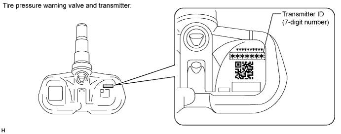
Confirm that the ID number on the transmitter and recorded transmitter ID match.
| Result | Proceed to |
| Match | A |
| Do not match | B |
|
| ||||
| A | |
|
| 5.REPLACE TIRE PRESSURE WARNING VALVE AND TRANSMITTER |
Replace the tire pressure warning valve and transmitter (Click here).
| NEXT | |
|
| 6.REGISTRATION OF TRANSMITTER ID |
Perform registration (Click here).
| NEXT | |
|
| 7.PERFORM INITIALIZATION |
Perform initialization (Click here).
| NEXT | |
|
| 8.CONFIRM TIRE INFLATION PRESSURE (DATA LIST) |
Turn the power switch off.
Connect the Techstream to the DLC3.
Turn the power switch on (IG) and turn the Techstream on.
Enter the following menus: Chassis / Tire Pressure Monitor/ Data List.
Check the values by referring to the table below.
| Tester Display | Measurement Item/Range | Normal Condition | Diagnostic Note |
| ID1 Tire Inflation Pressure | ID1 tire inflation pressure / min.: Absolute pressure / 0 kPa (0 kgf/cm2, 0 psi), Relative pressure / -100 kPa (-1 kgf/cm2, -14 psi) max.: Absolute pressure / 637.5 kPa (6.5 kgf/cm2, 92 psi), Relative pressure / 537.5 kPa (5.4 kgf/cm2, 78 psi) | Actual tire inflation pressure | If 0 kPa (0 kgf/cm2, 0 psi) is displayed for absolute pressure or -100 kPa (-1 kgf/cm2, -14 psi) is displayed for relative pressure, data has not been received.* |
| ID2 Tire Inflation Pressure | ID2 tire inflation pressure / min.: Absolute pressure / 0 kPa (0 kgf/cm2, 0 psi), Relative pressure / -100 kPa (-1 kgf/cm2, -14 psi) max.: Absolute pressure / 637.5 kPa (6.5 kgf/cm2, 92 psi), Relative pressure / 537.5 kPa (5.4 kgf/cm2, 78 psi) | Actual tire inflation pressure | If 0 kPa (0 kgf/cm2, 0 psi) is displayed for absolute pressure or -100 kPa (-1 kgf/cm2, -14 psi) is displayed for relative pressure, data has not been received.* |
| ID3 Tire Inflation Pressure | ID3 tire inflation pressure / min.: Absolute pressure / 0 kPa (0 kgf/cm2, 0 psi), Relative pressure / -100 kPa (-1 kgf/cm2, -14 psi) max.: Absolute pressure / 637.5 kPa (6.5 kgf/cm2, 92 psi), Relative pressure / 537.5 kPa (5.4 kgf/cm2, 78 psi) | Actual tire inflation pressure | If 0 kPa (0 kgf/cm2, 0 psi) is displayed for absolute pressure or -100 kPa (-1 kgf/cm2, -14 psi) is displayed for relative pressure, data has not been received.* |
| ID4 Tire Inflation Pressure | ID4 tire inflation pressure / min.: Absolute pressure / 0 kPa (0 kgf/cm2, 0 psi), Relative pressure / -100 kPa (-1 kgf/cm2, -14 psi) max.: Absolute pressure / 637.5 kPa (6.5 kgf/cm2, 92 psi), Relative pressure / 537.5 kPa (5.4 kgf/cm2, 78 psi) | Actual tire inflation pressure | If 0 kPa (0 kgf/cm2, 0 psi) is displayed for absolute pressure or -100 kPa (-1 kgf/cm2, -14 psi) is displayed for relative pressure, data has not been received.* |
| Result | Proceed to |
| Tire pressure values are not displayed. | A |
| All tire pressure readings are equal to specified values. | B |
|
| ||||
| A | |
|
| 9.REPLACE TIRE PRESSURE WARNING ANTENNA AND RECEIVER |
Replace the tire pressure warning antenna and receiver (Click here).
| NEXT | |
|
| 10.CONFIRM TIRE INFLATION PRESSURE (DATA LIST) |
Turn the power switch off.
Connect the Techstream to the DLC3.
Turn the power switch on (IG) and turn the Techstream on.
Enter the following menus: Chassis / Tire Pressure Monitor / Data List.
Check the values by referring to the table below.
| Tester Display | Measurement Item/Range | Normal Condition | Diagnostic Note |
| ID1 Tire Inflation Pressure | ID1 tire inflation pressure / min.: Absolute pressure / 0 kPa (0 kgf/cm2, 0 psi), Relative pressure / -100 kPa (-1 kgf/cm2, -14 psi) max.: Absolute pressure / 637.5 kPa (6.5 kgf/cm2, 92 psi), Relative pressure / 537.5 kPa (5.4 kgf/cm2, 78 psi) | Actual tire inflation pressure | If 0 kPa (0 kgf/cm2, 0 psi) is displayed for absolute pressure or -100 kPa (-1 kgf/cm2, -14 psi) is displayed for relative pressure, data has not been received.* |
| ID2 Tire Inflation Pressure | ID2 tire inflation pressure / min.: Absolute pressure / 0 kPa (0 kgf/cm2, 0 psi), Relative pressure / -100 kPa (-1 kgf/cm2, -14 psi) max.: Absolute pressure / 637.5 kPa (6.5 kgf/cm2, 92 psi), Relative pressure / 537.5 kPa (5.4 kgf/cm2, 78 psi) | Actual tire inflation pressure | If 0 kPa (0 kgf/cm2, 0 psi) is displayed for absolute pressure or -100 kPa (-1 kgf/cm2, -14 psi) is displayed for relative pressure, data has not been received.* |
| ID3 Tire Inflation Pressure | ID3 tire inflation pressure / min.: Absolute pressure / 0 kPa (0 kgf/cm2, 0 psi), Relative pressure / -100 kPa (-1 kgf/cm2, -14 psi) max.: Absolute pressure / 637.5 kPa (6.5 kgf/cm2, 92 psi), Relative pressure / 537.5 kPa (5.4 kgf/cm2, 78 psi) | Actual tire inflation pressure | If 0 kPa (0 kgf/cm2, 0 psi) is displayed for absolute pressure or -100 kPa (-1 kgf/cm2, -14 psi) is displayed for relative pressure, data has not been received.* |
| ID4 Tire Inflation Pressure | ID4 tire inflation pressure / min.: Absolute pressure / 0 kPa (0 kgf/cm2, 0 psi), Relative pressure / -100 kPa (-1 kgf/cm2, -14 psi) max.: Absolute pressure / 637.5 kPa (6.5 kgf/cm2, 92 psi), Relative pressure / 537.5 kPa (5.4 kgf/cm2, 78 psi) | Actual tire inflation pressure | If 0 kPa (0 kgf/cm2, 0 psi) is displayed for absolute pressure or -100 kPa (-1 kgf/cm2, -14 psi) is displayed for relative pressure, data has not been received.* |
| Result | Proceed to |
| All tire pressure readings are equal to specified values. | A |
| Tire pressure values are not displayed. | B |
|
| ||||
| A | ||
 | ||
| ||

