AUDIO AND VISUAL SYSTEM > Gateway ECU Communication Error |
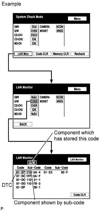
| 1.IDENTIFY COMPONENT SHOWN BY SUB-CODE |
|
Enter the diagnostic mode.
Press the "LAN Mon" switch to change to "LAN Monitor" mode.
Identify the component which has stored this code.
| NEXT | |
 |
| 2.CHECK POWER SOURCE CIRCUIT OF COMPONENT SHOWN BY SUB-CODE |
Inspect the power source circuit of the component shown by the sub-code.
If the power source circuit is operating normally, proceed to the next step.
| Component | Proceed to |
| Multi-display (110) | Multi-display power source circuit (Click here) |
| Stereo component amplifier (440) | Stereo component amplifier power source circuit (Click here) |
| Radio receiver (190) | Radio receiver power source circuit (Click here) |
| NEXT | |
|
| 3.INSPECT RADIO RECEIVER |
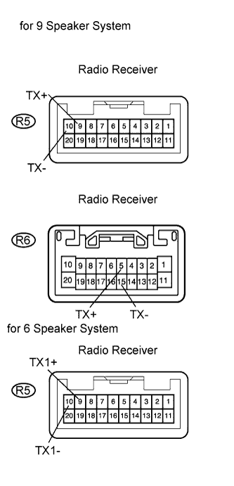 |
for 9 Speaker System:
Disconnect the R5 and R6 receiver connectors.
for 6 Speaker System:
Disconnect the R5 receiver connector.
Measure the resistance of the receiver.
| Tester Connection | Specified Condition |
| R5-9 (TX1+) - R5-10 (TX1-)*1 | 60 to 80 Ω |
| R5-9 (TX+) - R5-10 (TX-)*2 | 60 to 80 Ω |
| R6-5 (TX+) - R6-15 (TX-)*2 | 60 to 80 Ω |
|
| ||||
| OK | |
|
| 4.CHECK WIRE HARNESS (GATEWAY ECU - COMPONENT SHOWN BY SUB-CODE) |
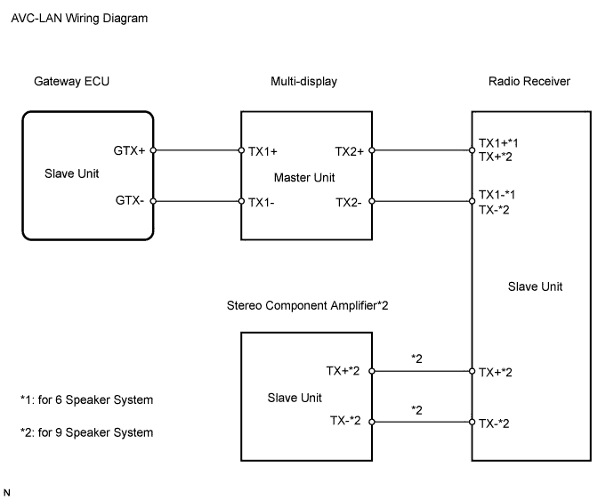
Referring to the AVC-LAN wiring diagram below, check the AVC-LAN circuit between the gateway ECU and the component shown by the sub-code.
Disconnect all connectors between the gateway ECU and the component shown by sub-code.
Check for an open or short in the AVC-LAN circuit between the gateway ECU and the component shown by the sub-code.
|
| ||||
| OK | |
|
| 5.REPLACE COMPONENT SHOWN BY SUB-CODE |
Replace the component shown by the sub-code with a normal one and check if the same problem occurs again.
|
| ||||
| OK | ||
 | ||
| ||
