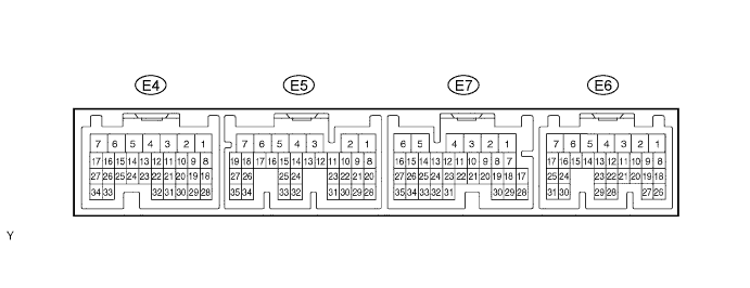
SFI SYSTEM > TERMINALS OF ECM |
| Symbols (Terminal No.) | Wiring Color | Terminal Description | Condition | STD Voltage (V) |
| BATT (E7-6) - E1 (E5-28) | R - BR | Battery | Always | 9 to 14 |
| +B (E7-4) - E1 (E5-28) | B - BR | Power source of ECM | Power switch ON (IG) | 9 to 14 |
| +BM (E7-5) - E1 (E5-28) | GR - BR | Power source of ETCS | Always | 9 to 14 |
| IGSW (E6-9) - E1 (E5-28) | O - BR | Power switch signal | Power switch ON (IG) | 9 to 14 |
| MREL (E7-7) - E1 (E5-28) | G - BR | Main relay control signal | Power switch ON (IG) | 9 to 14 |
| VC (E4-18) - E2 (E4-28) | R - BR | Power source of sensor (a specific voltage) | Power switch ON (IG) | 4.5 to 5.5 |
| NE+ (E4-33) - NE- (E4-34) | R - G | Crankshaft position sensor | Idling (during inspection mode) | Purge generation (Click here) |
| G2 (E4-26) - NE- (E4-34) | R - G | Camshaft position sensor | Idling (during inspection mode) | Purge generation (Click here) |
| VTA (E4-32) - E2 (E4-28) | P - BR | Throttle position sensor | Power switch ON (IG), Throttle valve fully closed | 0.5 to 1.2 |
| VTA (E4-32) - E2 (E4-28) | P - BR | Throttle position sensor | HV system ON, During active test to open throttle valve (Click here) | 3.2 to 4.8 |
| VTA2 (E4-31) - E2 (E4-28) | L - BR | Throttle position sensor | Power switch ON (IG), Accelerator pedal released | 2.0 to 2.9 |
| VTA2 (E4-31) - E2 (E4-28) | L - BR | Throttle position sensor | HV system ON, During active test to open throttle valve (Click here) | 4.6 to 5.5 |
| VG (E5-33) - EVG (E5-32) | G - R | Mass air flow meter | Idling (during inspection mode), A/C switch OFF | 1.0 to 1.5 |
| THA (E4-20) - E2 (E4-28) | W - BR | Intake air temperature sensor | Idling (during inspection mode), Intake air temperature at 20°C (68°F) | 0.5 to 3.4 |
| THW (E4-19) - E2 (E4-28) | W - BR | Engine coolant temperature sensor | Idling (during inspection mode), Engine coolant temperature at 80°C (176°F) | 0.2 to 1.0 |
| #10 (E4-2) - E01 (E4-7) | Y - BR | Injector | Power switch ON (IG) | 9 to 14 |
| #20 (E4-3) - E01 (E4-7) | B - BR | Injector | Power switch ON (IG) | 9 to 14 |
| #30 (E4-4) - E01 (E4-7) | L - BR | Injector | Power switch ON (IG) | 9 to 14 |
| #40 (E4-5) - E01 (E4-7) | R - BR | Injector | Power switch ON (IG) | 9 to 14 |
| IGT1 (E4-8) - E1 (E5-28) | Y - BR | Ignition coil No. 1 (#1) (Ignition signal) | Idling (during inspection mode) | Pulse generation (Click here) |
| IGT2 (E4-9) - E1 (E5-28) | W - BR | Ignition coil No. 1 (#2) (Ignition signal) | Idling (during inspection mode) | Pulse generation (Click here) |
| IGT3 (E4-10) - E1 (E5-28) | G - BR | Ignition coil No. 1 (#3) (Ignition signal) | Idling (during inspection mode) | Pulse generation (Click here) |
| IGT4 (E4-11) - E1 (E5-28) | Y - BR | Ignition coil No. 1 (#4) (Ignition signal) | Idling (during inspection mode) | Pulse generation (Click here) |
| KNK1 (E5-1) - EKNK (E5-2) | B - W | Knock sensor | Idling (during inspection mode) | Pulse generation (Click here) |
| IGF (E4-23) - E1 (E5-28) | B - BR | Ignition confirmation signal | Idling (during inspection mode) | Pulse generation (Click here) |
| A1A+ (E5-23) - E1 (E5-28) | G - BR | A/F sensor | Power switch ON (IG) | 3.0 to 3.6 |
| A1A- (E5-22) - E1 (E5-28) | R - BR | A/F sensor | Power switch ON (IG) | 2.7 to 3.3 |
| OX1B (E6-22) - E2 (E4-28) | Y - BR | Heated oxygen sensor | Maintain engine speed at 2,500 rpm for 2 minutes after warming up | Pulse generation |
| HA1A (E5-7) - E04 (E4-1) | Y - BR | A/F sensor heater | Idling (during inspection mode) | Below 3.0 |
| HA1A (E5-7) - E04 (E4-1) | Y - BR | A/F sensor heater | Power switch ON (IG) | 9 to 14 |
| HT1B (E6-6) - E03 (E6-7) | G - BR | Heated oxygen sensor heater | Idling (during inspection mode) | Below 3.0 |
| HT1B (E6-6) - E03 (E6-7) | G - BR | Heated oxygen sensor heater | Power switch ON (IG) | 9 to 14 |
| PTNK (E7-34) - E2 (E4-28) | Y - BR | Vapor pressure sensor | Power switch ON (IG) | 2.9 to 3.7 |
| PTNK (E7-34) - E2 (E4-28) | Y - BR | Vapor pressure sensor | Apply vacuum 4.0 kPa | Below 0.5 |
| EVP1 (E5-14) - E1 (E5-28) | R - BR | EVAP VSV | Power switch ON (IG) | 9 to 14 |
| TBP (E7-18) - E1 (E5-28) | R - BR | Tank bypass VSV | Power switch ON (IG) | 9 to 14 |
| M+ (E5-6) - E1 (E5-28) | L - BR | Throttle actuator control motor | Idling (during inspection mode) | Pulse generation |
| M- (E5-5) - E1 (E5-28) | P - BR | Throttle actuator control motor | Idling (during inspection mode) | Pulse generation |
| OCV+ (E4-15) - OCV- (E4-14) | Y - W | Camshaft timing oil control | Power switch ON (IG) | Pulse generation (Click here) |
| TAM (E7-21) - E2 (E4-28) | W - BR | Outside air temperature sensor | Ambient air temperature -40 to 140°C (-40 to 284°F) | 0.8 to 1.3 |
| MOPS (E5-15) - E1 (E5-28) | Y - BR | Engine oil pressure | Power switch ON (IG), not engine running | 9 to 14 |
| WBAD (E7-20) - E1 (E5-28) | R - BR | Water valve position signal | Power switch ON (IG) | 0.3 to 4.7 |
| THW2 (E7-33) - E2 (E4-28) | W - BR | Coolant heat storage tank outlet temperature sensor | Power switch ON (IG), Coolant temperature at 80°C (176°F) | 0.2 to 1.0 |
| WSL1 (E7-24) - WSL2 (E7-23) | Y - V | Water valve motor | Changing valve position | Pulse generation |
| WPL (E7-15) - E1 (E5-28) | V - BR | CHS water pump | Pre-heat mode | 0 to 2 |
| FAN (E7-8) - E1 (E5-28) | LG - BR | Cooling fan relay | Power switch ON (IG), Engine coolant temperature less than 94.5°C (202°F) | 9 to 14 |
| W (E6-18) - E1 (E5-28) | LG - BR | MIL | Idling (during inspection mode) | 9 to 14 |
| W (E6-18) - E1 (E5-28) | LG - BR | MIL | Power switch ON (IG) | Below 3.0 |
| FC (E6-10) - E1 (E5-28) | G - BR | Fuel pump control | Power switch ON (IG) | 9 to 14 |
| FC (E6-10) - E1 (E5-28) | G - BR | Fuel pump control | Power switch ON (IG) | Below 3.0 |
| TC (E6-14) - E1 (E5-28) | P - BR | Terminal TC of DLC3 | Power switch ON (IG) | 9 to 14 |
| NEO (E7-1) - E1 (E5-28) | LG - BR | Revolution signal | Idling (during inspection mode) | Pulse generation |
| GO (E7-2) - E1 (E5-28) | Y - BR | Revolution signal | Idling (during inspection mode) | Pulse generation |
| CANH (E6-31) - E1 (E5-28) | B - BR | CAN communication line | Power switch ON (IG) | Pulse generation |
| CANL (E6-30) - E1 (E5-28) | W - BR | CAN communication line | Power switch ON (IG) | Pulse generation |
| VPMP (E7-26) - E1 (E5-28) | V - BR | Vent valve (built into pump module) | Power switch ON (IG) | 9 to 14 |
| MPMP (E7-13) - E1 (E5-28) | P - BR | Vacuum pump (built into pump module) | Vacuum pump OFF | 0 to 3 |
| MPMP (E7-13) - E1 (E5-28) | P - BR | Vacuum pump (built into pump module) | Vacuum pump ON | 9 to 14 |
| PPMP (E7-30) - E1 (E5-28) | L - BR | Pressure sensor (built into pump module) | Power switch ON (IG) | 3 to 3.6 |