FRONT SUSPENSION FRONT SHOCK ABSORBER INSTALLATION
CAUTION / NOTICE / HINT
- HINT:
- ·
Use the same procedure for the RH side and LH side.
·The procedure listed below is for the LH side.
PROCEDURE

 1.INSTALL FRONT LOWER COIL SPRING INSULATOR (w/ Front Lower Coil Spring Insulator)
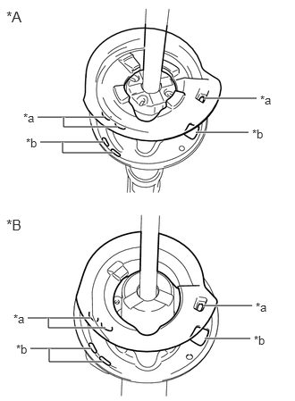
| *A | Shock Absorber Type A |
| *B | Shock Absorber Type B |
| *a | Positioning Pin |
| *b | Hole |
Install the front lower coil spring insulator to the front shock absorber assembly.
- NOTICE:
-
Make sure that each positioning pin of the front lower coil spring insulator is inserted into the hole in the front shock absorber.
48132
2.INSTALL FRONT COIL SPRING
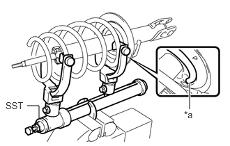
| *a | Lower End |
Using SST, compress the front coil spring.
- SST
- 09727-30021 (09727-00010, 09727-00021, 09727-00031)
- NOTICE:
-
Do not use an impact wrench. It will damage SST.
Install the front coil spring onto the front shock absorber assembly.
- NOTICE:
-
Make sure to fit the end of the spring that has the larger diameter into the front shock absorber lower seat.
- HINT:
-
Fit the lower end of the front coil spring into the gap of the front shock absorber lower seat.
48157C
3.INSTALL FRONT UPPER COIL SPRING INSULATOR (w/ Front Lower Coil Spring Insulator)
Shock Absorber Type A:
Install the front upper coil spring insulator to the front shock absorber assembly.
Shock Absorber Type B:
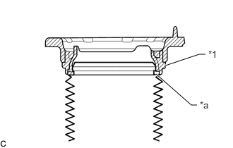
| *1 | Front Upper Coil Spring Insulator |
| *a | Top End of the Insulator (Shock Absorber Dust Cover) |
Install the front upper coil spring insulator to the front shock absorber assembly.
- NOTICE:
-
Make sure that the top end of the insulator (shock absorber dust cover) and the front upper coil spring insulator are securely attached.
48157C
4.INSTALL FRONT UPPER COIL SPRING INSULATOR (w/o Front Lower Coil Spring Insulator)
Install the front upper coil spring insulator to the front shock absorber assembly.
48304
5.INSTALL FRONT NO. 1 SPRING BUMPER SUB-ASSEMBLY (w/ Front Lower Coil Spring Insulator)
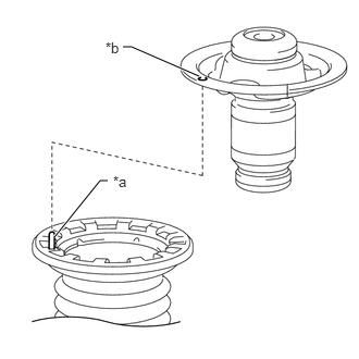
| *a | Protrusion |
| *b | Hole |
Install the front No. 1 spring bumper sub-assembly to the front shock absorber assembly.
- NOTICE:
-
When installing the front No. 1 spring bumper sub-assembly, first align the hole in the front No. 1 spring bumper sub-assembly with the protrusion of the front upper coil spring insulator.
- HINT:
-
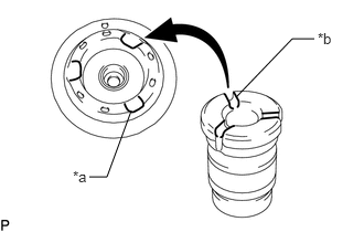 0.844,1.667 1.01,1.667 1.01,1.667 1.24,1.042 false 2.229,0.917 2.76,0.365 2.76,0.365 2.969,0.365 false 0.688,1.583 0.979,1.76 0.292,0.177 10 false *a 3,0.281 3.313,0.438 0.313,0.156 10 false *b
*a Rib Portion *b Air Discharge Groove
-
Visually check that the air discharge grooves of the front No. 1 spring bumper sub-assembly are aligned with the rib portions of the front spring seat.
48304
6.INSTALL FRONT NO. 1 SPRING BUMPER SUB-ASSEMBLY (w/o Front Lower Coil Spring Insulator)
Install the front No. 1 spring bumper sub-assembly to the front shock absorber assembly.
- HINT:
-
0.844,1.667 1.01,1.667 1.01,1.667 1.24,1.042 false 2.229,0.917 2.76,0.365 2.76,0.365 2.969,0.365 false 0.688,1.583 0.979,1.76 0.292,0.177 10 false *a 3,0.281 3.313,0.438 0.313,0.156 10 false *b
*a Rib Portion *b Air Discharge Groove
-
Visually check that the air discharge grooves of the front No. 1 spring bumper sub-assembly are aligned with the rib portions of the front spring seat.
48609E
7.INSTALL FRONT SUPPORT TO FRONT SHOCK ABSORBER NUT
Temporarily tighten a new front support to front shock absorber nut.
Remove SST from the front coil spring.
- NOTICE:
-
Do not use an impact wrench. It will damage SST.
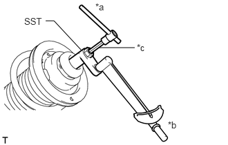
| *a | Hold |
| *b | Turn |
| *c | Long Hexagon Socket Wrench |
Using SST and long hexagon socket wrench, hold the shock absorber rod and tighten the front support to front shock absorber nut.
- SST
- 09729-97202
- Torque:
- without SST : 33 N*m (340 kgf*cm, 25 ft.*lbf)
- with SST : 29 N*m (300 kgf*cm, 22 ft.*lbf)
- HINT:
- ·
This torque value is effective when SST is parallel to the torque wrench.
·This torque value can be obtained by using a torque wrench with a fulcrum length of 300 mm (11.8 in.) and SST with a fulcrum length of 40 mm (1.57 in.).
·If using a torque wrench with a length that is not 300 mm (11.8 in.), calculate the torque specification for the torque wrench and SST based on the "without SST" torque specification (Click hereGeneral>INTRODUCTION>REPAIR INSTRUCTION>PRECAUTION).
48609
8.INSTALL FRONT SUSPENSION SUPPORT SUB-ASSEMBLY
48157C
9.CONNECT FRONT UPPER COIL SPRING INSULATOR (Shock Absorber Type B)
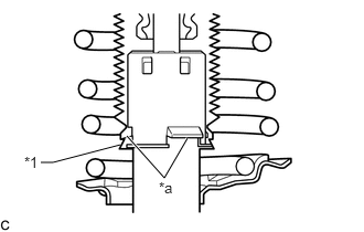
| *1 | Front Upper Coil Spring Insulator |
| *a | Claw |
Connect the end of the insulator of the front upper coil spring insulator with the claws of the front shock absorber assembly.
- NOTICE:
- ·
Make sure that the end of the insulator is securely attached to the claws of the front shock absorber assembly.
·Make sure there is no excessive damage to the bellows of the insulator.
·Do not allow oil, grease, etc. to contact the insulator.
·If there is oil or grease on the insulator, wipe clean with a cloth. Do not use an alcohol based cleaner.
10.TEMPORARILY TIGHTEN FRONT SHOCK ABSORBER WITH COIL SPRING
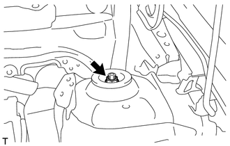
Temporarily tighten a new nut through the front No. 2 suspension support.
Install the front shock absorber with coil spring to the steering knuckle and insert the 2 bolts and 2 nuts.
- Torque:
- 164 N*m (1672 kgf*cm, 121 ft.*lbf)
- NOTICE:
-
When installing the nuts, keep the bolts from rotating.
- HINT:
-
The bolt can be inserted in either direction, however, make sure that they are installed in the same direction.
47313A
11.INSTALL FRONT FLEXIBLE HOSE
Install the front flexible hose and front speed sensor with the bolt.
- Torque:
- 29 N*m (300 kgf*cm, 22 ft.*lbf)
- NOTICE:
-
Do not twist the front flexible hose and front speed sensor when installing it.
48810
12.INSTALL FRONT STABILIZER LINK ASSEMBLY
Install the front stabilizer link assembly to the front shock absorber assembly with the nut.
- Torque:
- 74 N*m (755 kgf*cm, 55 ft.*lbf)
- HINT:
-
Use a hexagon socket wrench to hold the stud.
13.INSTALL FRONT WHEEL
- Torque:
- 103 N*m (1050 kgf*cm, 76 ft.*lbf)
14.FULLY TIGHTEN FRONT SHOCK ABSORBER WITH COIL SPRING
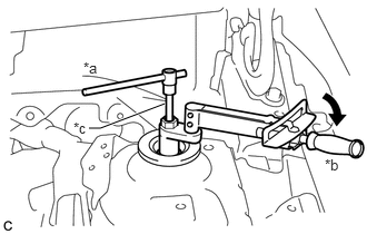
| *a | Hold |
| *b | Turn |
| *c | Long Hexagon Socket Wrench |
Using SST and long hexagon socket wrench, hold the front shock absorber rod and tighten the nut.
- SST
- 09729-97202
- Torque:
- with SST : 55 N*m (561 kgf*cm, 41 ft.*lbf)
- without SST : 49 N*m (503 kgf*cm, 36 ft.*lbf)
- HINT:
- ·
This torque value is effective when SST is parallel to the torque wrench.
·This torque value can be obtained by using a torque wrench with a fulcrum length of 345 mm (1.13 ft.) and SST with a fulcrum length of 40 mm (1.57 in.).
·If using a torque wrench with a length that is not 345 mm (1.13 ft.), calculate the torque specification for the torque wrench and SST based on the "without SST" torque specification (Click hereGeneral>INTRODUCTION>REPAIR INSTRUCTION>PRECAUTION).
48684B
15.INSTALL FRONT SUSPENSION SUPPORT DUST COVER
55701J
16.INSTALL OUTER COWL TOP PANEL SUB-ASSEMBLY (for LHD)
55701J
17.INSTALL OUTER COWL TOP PANEL SUB-ASSEMBLY (for RHD)
55815E
18.INSTALL FRONT NO. 1 VENTILATOR SEAL (for LHD)
55815E
19.INSTALL FRONT NO. 1 VENTILATOR SEAL (for RHD)
55735B
20.INSTALL FRONT AIR SHUTTER SEAL (for LHD)
55735B
21.INSTALL FRONT AIR SHUTTER SEAL (for RHD)
55722C
22.INSTALL INNER COWL TOP TO COWL BRACE (for LHD)
55722C
23.INSTALL INNER COWL TOP TO COWL BRACE (for RHD)
24.INSTALL WINDSHIELD WIPER MOTOR AND LINK ASSEMBLY
25.STABILIZE SUSPENSION
26.INSPECT AND ADJUST FRONT WHEEL ALIGNMENT