BRAKE (REAR) REAR BRAKE INSTALLATION
CAUTION / NOTICE / HINT
- HINT:
- ·
Use the same procedure for the LH side and RH side.
·The following procedure is for the LH side.
PROCEDURE

 47570
1.INSTALL REAR WHEEL BRAKE CYLINDER ASSEMBLY
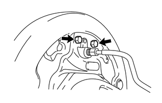
Install the rear wheel brake cylinder assembly to the backing plate with the 2 bolts.
- Torque:
- 9.8 N*m (100 kgf*cm, 87 in.*lbf)
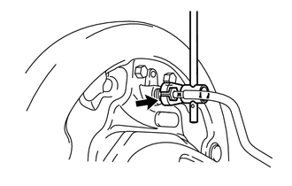
Using a union nut wrench, connect the brake line to the rear wheel brake cylinder assembly.
- Torque:
- 15 N*m (155 kgf*cm, 11 ft.*lbf)
- NOTICE:
- ·
Use a torque wrench with a fulcrum length of 250 mm (9.84 in.).
·This torque value is effective when the union nut wrench is parallel to the torque wrench.
·Use the formula to calculate special torque values for situations where the union nut wrench is combined with a torque wrench (See page General>INTRODUCTION>REPAIR INSTRUCTION>PRECAUTION).
47547R
2.TEMPORARILY TIGHTEN REAR DRUM BRAKE BLEEDER PLUG
- HINT:
-
Fully tighten the rear drum brake bleeder plug after bleeding any air left in the system.
47548R
3.INSTALL REAR DRUM BRAKE BLEEDER PLUG CAP
47644A
4.INSTALL REAR BRAKE AUTOMATIC ADJUST LEVER
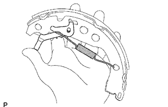
Install the rear brake automatic adjust lever and automatic adjust lever tension spring to the rear brake shoe (front).
46430
5.CONNECT NO. 3 PARKING BRAKE CABLE ASSEMBLY
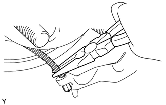
Using needle-nose pliers, install the No. 3 parking brake cable assembly to the rear brake parking brake shoe lever sub-assembly.
04943A
6.INSTALL REAR BRAKE STRUT KIT
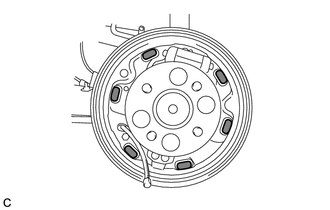
Apply high temperature grease to the surface of the backing plate that contacts the shoes as shown in the illustration.

|
High Temperature Grease |
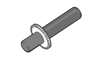
Apply high temperature grease to the adjustment bolt.
|
|
High Temperature Grease |
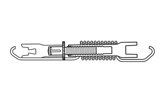
Assemble the rear brake strut kit as shown in the illustration.
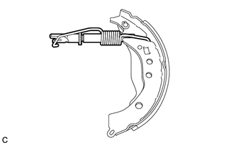
Install the rear brake strut kit to the rear brake shoe.
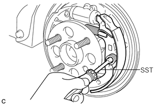
Using SST, install the rear brake shoe, shoe hold down spring pin, shoe hold down spring and shoe hold down spring cup.
- SST
- 09718-00011
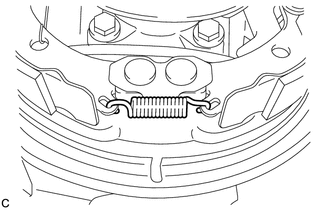
Install the shoe tension spring to the rear brake shoe.
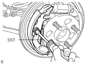
Using SST, install the rear brake shoe, shoe hold down spring pin, shoe hold down spring and shoe hold down spring cup.
- SST
- 09718-00011
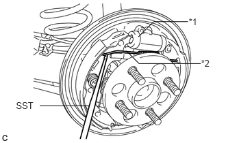
Using SST, install the tension spring to the rear brake shoe.
| *1 | Wheel Cylinder Boot |
| *2 | Tension Spring |
- SST
- 09921-00011
- NOTICE:
-
Do not damage the wheel cylinder boot.
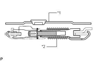
Inspect the rear brake strut set is installed properly as shown in the illustration.
| *1 | Back Plate |
| *2 | Rear Brake Strut Set |
7.INSPECT REAR DRUM BRAKE
Inspect that each part is installed properly as shown in the illustration.
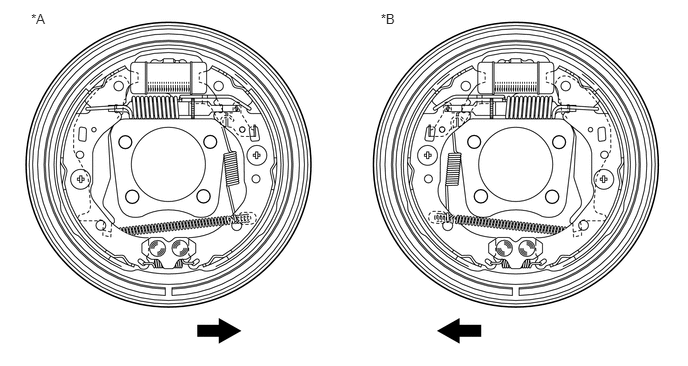
| *A | RH Side | *B | LH Side |

|
Front of the Vehicle | - | - |
- NOTICE:
-
There should be no oil or grease adhering to the friction surfaces of the shoe lining or the drum.
42403
8.INSTALL REAR BRAKE DRUM SUB-ASSEMBLY
Install the rear brake drum.
9.ADJUST REAR DRUM BRAKE SHOE CLEARANCE
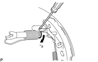
Temporarily install the 2 wheel nuts.
|
|
Expand |
Remove the shoe adjusting hole plug, and turn the adjuster to expand the shoe until the drum locks.
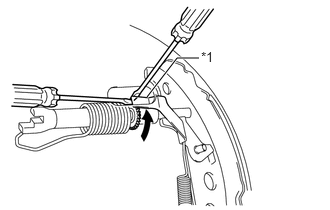
Hold the automatic adjust lever away from the adjuster, and contract the brake shoe by turning the adjust bolt using another screwdriver until the drum can rotate smoothly.
| *1 | Automatic Adjust Lever |
|
|
Contract |
Install the hole plug.
10.CONNECT CABLE TO NEGATIVE AUXILIARY BATTERY TERMINAL
Connect the cable to the negative (-) auxiliary battery terminal (See page Power Source / Network>1NZ-FXE BATTERY / CHARGING>AUXILIARY BATTERY>INSTALLATION).
Perform the following procedure if air bleeding is not necessary:
Connect the reservoir level switch connector.
Clear the DTCs (See page Brake>BRAKE CONTROL / DYNAMIC CONTROL SYSTEMS>ELECTRONICALLY CONTROLLED BRAKE SYSTEM>DTC CHECK / CLEAR).
11.BLEED BRAKE LINE
12.ADJUST PARKING BRAKE
13.INSTALL REAR WHEEL
- Torque:
- 103 N*m (1050 kgf*cm, 76 ft.*lbf)