1NZ-FXE ENGINE MECHANICAL CYLINDER HEAD GASKET REMOVAL
PROCEDURE

 15100
1.REMOVE TIMING CHAIN COVER
17138B
2.REMOVE INTAKE MANIFOLD STAY
17111
3.REMOVE INTAKE MANIFOLD
17167
4.REMOVE NO. 1 EXHAUST MANIFOLD HEAT INSULATOR
25591
5.REMOVE MANIFOLD SUPPORT BRACKET
17141
6.REMOVE EXHAUST MANIFOLD
13540
7.REMOVE NO. 1 CHAIN TENSIONER ASSEMBLY
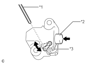
Turn the stopper plate of the No. 1 chain tensioner assembly clockwise and push in the plunger with the lock released.
| *1 | Hexagon Wrench |
| *2 | Plunger |
| *3 | Stopper Plate |
Turn the stopper plate of the No. 1 chain tensioner assembly counterclockwise and insert a hexagon wrench into the hole in the stopper plate to lock with the plunger pushed in.
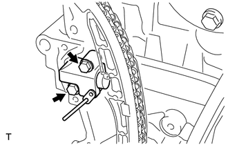
Remove the 2 bolts and No. 1 chain tensioner assembly.
- NOTICE:
-
Do not rotate the crankshaft with the No. 1 chain tensioner removed.
13559
8.REMOVE CHAIN TENSIONER SLIPPER
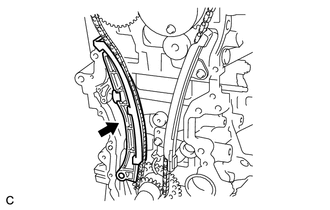
Remove the chain tensioner slipper.
13561
9.REMOVE NO. 1 CHAIN VIBRATION DAMPER
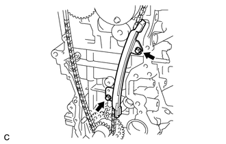
Remove the 2 bolts and No. 1 chain vibration damper.
13506
10.REMOVE CHAIN SUB-ASSEMBLY
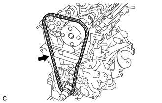
Remove the chain sub-assembly.
- NOTICE:
-
When rotating the camshaft with the chain sub-assembly removed, rotate the crankshaft counterclockwise 40° from TDC and align the oil jet hole with the paint mark to prevent the pistons from coming into contact with the valves.
11.REMOVE CAMSHAFT
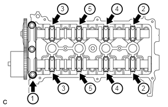
Using several steps, uniformly loosen and remove the 19 bolts in the sequence shown in the illustration, then remove the No. 1 camshaft bearing cap and 8 No. 2 camshaft bearing caps.
- NOTICE:
-
Uniformly loosen the bolts while keeping the camshaft level.
Remove the camshaft and No. 2 camshaft.
11101
12.REMOVE CYLINDER HEAD SUB-ASSEMBLY
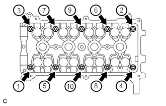
Using several steps, uniformly loosen and remove the 10 cylinder head bolts and 10 washers with an 8 mm bi-hexagon wrench in the sequence shown in the illustration.
- NOTICE:
- ·
When removing the cylinder head bolt, do not drop the washer into the cylinder head sub-assembly.
·Removing the bolts in the wrong order may cause damage to the cylinder head sub-assembly.
Remove the cylinder head sub-assembly.
11115
13.REMOVE CYLINDER HEAD GASKET
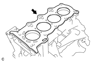
Remove the cylinder head gasket from the cylinder block.