2ZR-FXE EMISSION CONTROL EGR COOLER INSTALLATION
PROCEDURE

 25601L
1.INSTALL EGR WITH COOLER PIPE SUB-ASSEMBLY
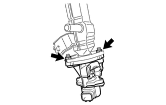
Temporarily install a new gasket and EGR valve assembly to the EGR cooler assembly with the 2 nuts.
Install a new gasket and set the EGR valve with cooler assembly in place.
Using an E8 "TORX" socket wrench, install the 4 stud bolts.
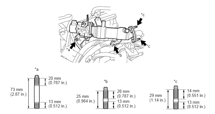
| *a | Stud Bolt A | *b | Stud Bolt B |
| *c | Stud Bolt C | - | - |
- Torque:
- Stud Bolt A and Stud Bolt B : 9.5 N*m (97 kgf*cm, 84 in.*lbf)
- Stud Bolt C : 5.0 N*m (51 kgf*cm, 44 in.*lbf)
If a stud bolt is deformed or the threads are damaged, replace it.
Temporarily install the 2 nuts (B), 2 nuts (C) and bolt.
- HINT:
-
The type B nut and type C nut are non-reusable.
Tighten the 2 nuts (A).
- Torque:
- 21 N*m (214 kgf*cm, 15 ft.*lbf)
Tighten the 2 nuts (B) and bolt.
- Torque:
- 21 N*m (214 kgf*cm, 15 ft.*lbf)
- NOTICE:
-
Make sure that all installation surfaces of the EGR valve with cooler assembly are in even contact when tightening the bolt and nuts.
Tighten the 2 nuts (C).
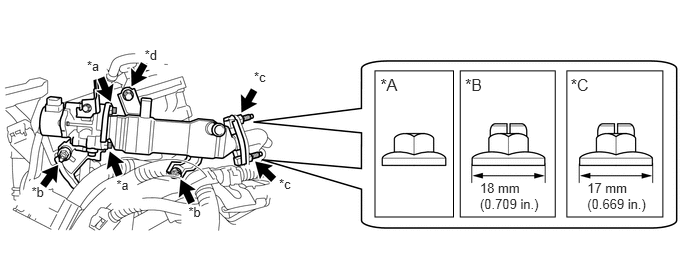
| *A | Type A | *B | Type B |
| *C | Type C | - | - |
| *a | Nut A | *b | Nut B |
| *c | Nut C | *d | Bolt |
- Torque:
- Type A : 21 N*m (214 kgf*cm, 15 ft.*lbf)
- Type B : 37 N*m (377 kgf*cm, 27 ft.*lbf)
- Type C : 26 N*m (265 kgf*cm, 19 ft.*lbf)
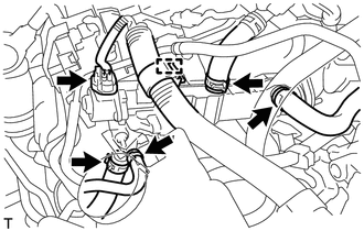
Connect the EGR valve assembly connector and engage the wire harness clamp.
Connect the 4 water hoses to the EGR valve assembly and slide the 4 clips to secure them.
25610
2.INSTALL EGR PIPE ASSEMBLY
3.INSTALL AIR CLEANER CASE
17750A
4.INSTALL INLET AIR CLEANER ASSEMBLY
17705
5.INSTALL AIR CLEANER CAP SUB-ASSEMBLY
11212
6.INSTALL NO. 2 CYLINDER HEAD COVER
7.ADD COOLANT (for Engine)
8.INSPECT FOR COOLANT LEAK (for Engine)
55701J
9.INSTALL OUTER COWL TOP PANEL SUB-ASSEMBLY (for LHD)
55701J
10.INSTALL OUTER COWL TOP PANEL SUB-ASSEMBLY (for RHD)
55736D
11.INSTALL COWL BODY MOUNTING REINFORCEMENT LH (for LHD)
55735C
12.INSTALL COWL BODY MOUNTING REINFORCEMENT RH (for RHD)
13.INSTALL WINDSHIELD WIPER MOTOR AND LINK ASSEMBLY