PARKING BRAKE PARKING BRAKE PEDAL(for RHD) REMOVAL
CAUTION / NOTICE / HINT
- NOTICE:
-
While the auxiliary battery is connected, even if the power switch is off, the brake control system activates when the brake pedal is depressed or any door courtesy switch is turned on. Therefore, when servicing brake system components, do not depress the brake pedal or open/close the doors while the auxiliary battery is connected.
PROCEDURE

 G9510
1.REMOVE HV BATTERY
67913
2.REMOVE FRONT DOOR SCUFF PLATE RH
- HINT:
-
Use the same procedure as for the LH side (See page Vehicle Interior>INTERIOR PANELS / TRIM>ROOF HEADLINING>REMOVAL).
62111C
3.REMOVE COWL SIDE TRIM SUB-ASSEMBLY RH
- HINT:
-
Use the same procedure as for the LH side (See page Vehicle Interior>INTERIOR PANELS / TRIM>ROOF HEADLINING>REMOVAL).
62311B
4.REMOVE FRONT DOOR OPENING TRIM WEATHERSTRIP RH
- HINT:
-
Use the same procedure as for the LH side (See page Vehicle Interior>INTERIOR PANELS / TRIM>ROOF HEADLINING>REMOVAL).
67917A
5.REMOVE REAR DOOR SCUFF PLATE RH
- HINT:
-
Use the same procedure as for the LH side (See page Vehicle Interior>INTERIOR PANELS / TRIM>ROOF HEADLINING>REMOVAL).
62331A
6.REMOVE REAR DOOR OPENING TRIM WEATHERSTRIP RH
- HINT:
-
Use the same procedure as for the LH side (See page Vehicle Interior>INTERIOR PANELS / TRIM>ROOF HEADLINING>REMOVAL).
73233
7.REMOVE LAP BELT OUTER ANCHOR COVER (for RH Side)
- HINT:
-
Use the same procedure as for the LH side (See page Vehicle Interior>SEAT BELT>FRONT SEAT OUTER BELT ASSEMBLY>REMOVAL).
73210
8.DISCONNECT FRONT SEAT OUTER BELT ASSEMBLY RH
- HINT:
-
Use the same procedure as for the LH side (See page Vehicle Interior>SEAT BELT>FRONT SEAT OUTER BELT ASSEMBLY>REMOVAL).
62413A
9.REMOVE CENTER PILLAR LOWER GARNISH RH
- HINT:
-
Use the same procedure as for the LH side (See page Vehicle Interior>INTERIOR PANELS / TRIM>ROOF HEADLINING>REMOVAL).
77306
10.REMOVE FUEL LID LOCK OPEN LEVER SUB-ASSEMBLY
87289A
11.REMOVE REAR NO. 1 HEATER REGISTER BEZEL
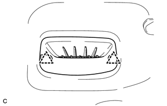
Remove the 2 clips and rear No. 1 heater register bezel.
G92D2
12.REMOVE NO. 2 HYBRID BATTERY INTAKE DUCT
Turn back the front floor carpet to a position where the No. 2 hybrid battery intake duct can be removed.
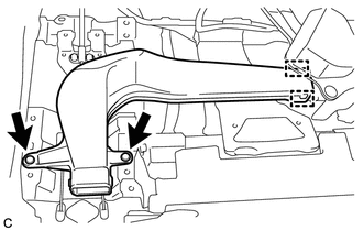
Remove the 2 clips.
Disengage the 2 guides and remove the No. 2 hybrid battery intake duct.
13.REMOVE INTEGRATION CONTROL AND PANEL
- HINT:
-
Use the same procedure as for LHD (See page Vehicle Interior>INTERIOR PANELS / TRIM>UPPER INSTRUMENT PANEL>REMOVAL).
55431B
14.REMOVE UPPER INSTRUMENT PANEL FINISH PANEL
- HINT:
-
Use the same procedure as for LHD (See page Vehicle Interior>INTERIOR PANELS / TRIM>UPPER INSTRUMENT PANEL>REMOVAL).
55480D
15.REMOVE LOWER INSTRUMENT PANEL FINISH PANEL ASSEMBLY
- HINT:
-
Use the same procedure as for LHD (See page Vehicle Interior>INTERIOR PANELS / TRIM>UPPER INSTRUMENT PANEL>REMOVAL).
55440D
16.REMOVE INSTRUMENT PANEL BOX ASSEMBLY
- HINT:
-
Use the same procedure as for LHD (See page Vehicle Interior>INTERIOR PANELS / TRIM>UPPER INSTRUMENT PANEL>REMOVAL).
55550
17.REMOVE GLOVE COMPARTMENT DOOR ASSEMBLY
- HINT:
-
Use the same procedure as for LHD (See page Vehicle Interior>INTERIOR PANELS / TRIM>LOWER INSTRUMENT PANEL>REMOVAL).
18.REMOVE LOWER INSTRUMENT PANEL FINISH PANEL SUB-ASSEMBLY
- HINT:
-
Use the same procedure as for LHD (See page Vehicle Interior>INTERIOR PANELS / TRIM>LOWER INSTRUMENT PANEL>REMOVAL).
55606
19.REMOVE NO. 1 INSTRUMENT PANEL UNDER COVER SUB-ASSEMBLY
- HINT:
-
Use the same procedure as for LHD (See page Vehicle Interior>INTERIOR PANELS / TRIM>LOWER INSTRUMENT PANEL>REMOVAL).
73900
20.REMOVE LOWER NO. 1 INSTRUMENT PANEL AIRBAG ASSEMBLY
- HINT:
-
Use the same procedure as for LHD (See page Vehicle Interior>SUPPLEMENTAL RESTRAINT SYSTEMS>KNEE AIRBAG ASSEMBLY>REMOVAL).
87201
21.REMOVE NO. 1 AIR DUCT SUB-ASSEMBLY
46441
22.LOOSEN ADJUSTING NUT
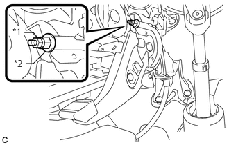
Remove the lock nut and loosen the adjusting nut.
| *1 | Lock Nut |
| *2 | Adjusting Nut |
46302
23.SEPARATE NO. 1 PARKING BRAKE PULL ROD SUB-ASSEMBLY
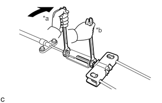
Separate the No. 1 parking brake pull rod sub-assembly from the parking brake control pedal assembly as shown in the illustration.
| *a | Turn |
| *b | Hold |
46200
24.REMOVE PARKING BRAKE CONTROL PEDAL ASSEMBLY
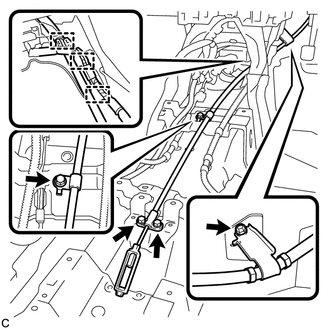
Remove the 4 bolts and separate the No. 1 parking brake cable assembly.
Disengage the 2 wire harness clamps.
Remove the No. 1 parking brake cable assembly from the clamp.
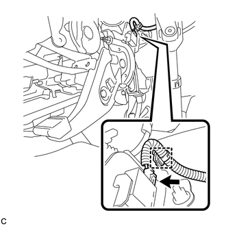
Disconnect the parking brake switch connector.
Disengage the wire harness clamp.
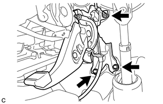
Remove the 2 bolts, nut and parking brake control pedal assembly.