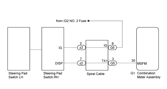
DTC B1504 Lost Communication with Steering SW |
| DTC No. | DTC Detection Condition | Trouble Area |
| B1504 | When the IG voltage is 9.5 V or more and power switch on (IG) and the following condition is detected:
|
|
| 1.READ VALUE USING TECHSTREAM (MULTI DISPLAY SELECT SWITCH) |
Connect the Techstream to the DLC3.
Turn the power switch on (IG).
Turn the Techstream on.
Enter the following menus: Body Electrical / Combination Meter / Data List.
Check the values by referring to the table below.
| Tester Display | Measurement Item/Range | Normal Condition | Diagnostic Note |
| Multi Display Select Switch | DISP switch in the steering pad switch assembly)OFF or ON | OFF: DISP switch in the steering pad switch assembly not pressed | - |
| ON: DISP switch in the steering pad switch assembly pressed | - | ||
| Drive Monitor Reset SW | TRIP switch in the steering pad switch assembly/OFF or ON | OFF: TRIP switch in the steering pad switch assembly not pressed | - |
| ON: TRIP switch in the steering pad switch assembly pressed more than 1 second | - |
|
| ||||
| OK | ||
 | ||
| ||
| 2.CHECK SPIRAL CABLE |
Check the spiral cable (Click here).
|
| ||||
| OK | |
 |
| 3.CHECK HARNESS AND CONNECTOR (COMBINATION METER ASSEMBLY - STEERING PAD SWITCH RH) |
Disconnect the G1 combination meter assembly connector.
Disconnect the z2 steering pad switch RH connector.
Measure the voltage according to the value(s) in the table below.
| Tester Connection | Condition | Specified Condition |
| z2-2 (IG) - Body ground | Power switch off | Below 1 V |
| z2-2 (IG) - Body ground | Power switch on (IG) | 11 to 14 V |
Measure the resistance according to the value(s) in the table below.
| Tester Connection | Condition | Specified Condition |
| z2-7 (DISP) - G1-30 (MSFM) | Always | Below 1 Ω |
| G1-30 (MSFM) - Body ground | Always | 10 kΩ or higher |
|
| ||||
| OK | |
|
| 4.REPLACE STEERING PAD SWITCH RH |
Replace the steering pad switch RH with a new or a known good one (Click here)
|
| ||||
| OK | ||
| ||
| ||
| 5.REPLACE STEERING PAD SWITCH LH |
Replace the steering pad switch LH with a new or a known good one (Click here).
|
| ||||
| OK | ||
| ||
| ||

