| NEXT | |
 |
CAN COMMUNICATION SYSTEM > HOW TO PROCEED WITH TROUBLESHOOTING |
| PRECAUTIONS WHEN TROUBLESHOOTING |
CAN communication DTCs are output for CAN main bus and CAN branch malfunctions as well as for internal malfunctions or power source malfunctions of ECUs or sensors for systems using CAN communication. Therefore, when DTCs for internal malfunctions or power source malfunctions of corresponding systems are output at the same time as CAN communication DTCs, troubleshoot according to the internal malfunction and power source malfunction DTCs.
The DLC3 branch and V bus main bus circuits can be checked for malfunctions by inspecting at the DLC3 terminals using a electrical tester.
An open in a branch for ECUs or sensors that are connected to the CAN main bus can be checked by performing a CAN bus check using the Techstream. (This inspection is possible when the DLC3 branch and V bus main bus lines are normal.)
If the V bus had a communication error, the probable ECU or sensor for which communication stopped can be determined using the combination of communication DTCs (DTCs that start with U) that are output.
A malfunction of sub bus 15 can be determined based on the number of DTCs stored by the ECM, power management control ECU and brake booster with master cylinder assembly (skid control ECU).
If a sub bus has a communication error, the gateway function equipped ECU (sub bus monitor ECU) detects it and stores DTCs related to the error.
When an open circuit is detected, before disconnecting related connectors for inspection, push in on the connector body to check that the connector is not loose or disconnected.
When a connector is disconnected, check that the terminals and connector body are not cracked, deformed or corroded.
| 1.VEHICLE BROUGHT TO WORKSHOP |
| |||||
| 2.CUSTOMER PROBLEM ANALYSIS |
It is useful to confirm the symptoms and the conditions in which the vehicle was operating at the time when a malfunction occurred. This helps to narrow down the malfunctioning part.
| Symptom |
|
| Meter warning lights |
|
| |||||
| 3.CHECK TECHSTREAM OPERATION |
Connect the Techstream to the DLC3.
Turn the ignition switch ON.
Turn the Techstream on.
Check that the Techstream and ECUs can communicate with the ignition switch ON.
| Result | Proceed to |
| OK (Communication between the Techstream and the vehicle is possible.) | A |
| OK (Communication between the Techstream and the vehicle is impossible but communication is possible when connected to another vehicle.) | B |
| NG (Communication is not possible between the Techstream and the vehicle, nor between the Techstream and another vehicle.) | C |
|
| ||||
|
| ||||
| |||||
| 4.CHECK DTC |
Using the Techstream, perform Health Check to read current and history DTCs and record them.
Read the freeze frame data using the Techstream and record it.
| |||||
| 5.CHECK COMMUNICATION MALFUNCTION CHECK (CONNECTION STATUS CHECK USING TECHSTREAM) |
Select "Communication Malfunction Check" from the screen on the Techstream.
Record all the DTCs stored for ECUs and sensors.
| |||||
| 6.CHECK CAN BUS CHECK (CONNECTION STATUS CHECK USING TECHSTREAM) |
Based on the vehicle equipment and specifications, confirm the systems that use CAN communication (Click here).
Select "CAN Bus Check" from the screen on the Techstream.
Observe the screen for approximately 2 minutes to check the ECUs and sensors displayed on the screen.
| |||||
| 7.CHECK DLC3 BRANCH LINE AND V BUS MAIN LINE (CANH - CANL) |
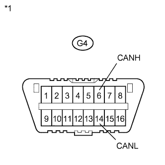 |
Disconnect the cable from the negative (-) auxiliary battery terminal.
Measure the resistance according to the value(s) in the table below.
| Tester Connection | Condition | Specified Condition |
| G4-6 (CANH) - G4-14 (CANL) | Cable disconnected from negative (-) auxiliary battery terminal | 54 to 69 Ω |
| *1 | DLC3 |
| Result | Proceed to |
| OK | A |
| NG (70 Ω or higher) | B |
| NG (Below 54 Ω) | C |
|
| ||||
|
| ||||
| |||||
| 8.CHECK FOR SHORT TO GND IN V BUS (CANH, CANL - CG) |
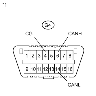 |
Measure the resistance according to the value(s) in the table below.
| Tester Connection | Condition | Specified Condition |
| G4-6 (CANH) - G4-4 (CG) | Cable disconnected from negative (-) auxiliary battery terminal | 200 Ω or higher |
| G4-14 (CANL) - G4-4 (CG) | Cable disconnected from negative (-) auxiliary battery terminal | 200 Ω or higher |
| *1 | DLC3 |
|
| ||||
| |||||
| 9.CHECK FOR SHORT TO +B IN V BUS (CANH, CANL - BAT) |
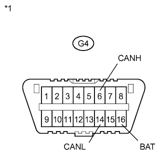 |
Measure the resistance according to the value(s) in the table below.
| Tester Connection | Condition | Specified Condition |
| G4-6 (CANH) - G4-16 (BAT) | Cable disconnected from negative (-) auxiliary battery terminal | 6 kΩ or higher |
| G4-14 (CANL) - G4-16 (BAT) | Cable disconnected from negative (-) auxiliary battery terminal | 6 kΩ or higher |
| *1 | DLC3 |
|
| ||||
| |||||
| 10.CHECK RESULT OF CAN BUS CHECK (CONNECTION STATUS CHECK USING TECHSTREAM) |
Inspect or repair the probable malfunctioning part based on the check result of step 6 (the step in which CAN Bus Check was performed).
| Result | Proceed to |
| All ECUs and sensors connected to the CAN communication system are displayed on the screen. (CAN bus circuit is currently normal.) | A |
| When the V bus is selected using the drop down list, all the ECUs and sensors connected to the V bus are displayed on the screen, but when sub bus 15 is selected, no connected ECUs or sensors are displayed. (Open or short in sub bus 15 main lines.) | B |
| No ECUs or sensors connected to the ECM or sub bus 15 are displayed on the screen. (Open in ECM main lines or ECM malfunction.) | C |
| One of the ECUs and sensors connected to the V Bus is not displayed on the screen. (Open in ECU or sensor branch lines, or communication is interrupted.) | D |
| One of the ECUs and sensors connected to sub bus 15 is not displayed on the screen. (Open in ECU or sensor branch lines, or communication is interrupted.) | E |
| In addition to ECUs and sensors which are connected to the CAN communication system but are not displayed on the screen, there are ECUs or sensors for which the detection status changes (changes between detected and not detected) during the inspection. (Open in one side of ECU or sensor branch lines.) | F |
|
| ||||
|
| ||||
|
| ||||
|
| ||||
|
| ||||
| |||||
| 11.CHECK RESULT OF CHECK COMMUNICATION MALFUNCTION CHECK (SELECT THE MALFUNCTIONING BUS) |
Inspect or repair the probable malfunctioning part based on the check result of step 5 (the step in which checking for communication malfunction DTCs was performed).
| Result | Proceed to |
| A |
| ECUs connected to sub bus 15 store communication error DTCs. (A malfunction occurred in sub bus 15.)
| B |
| The power management control ECU outputs only DTC U0129 (Lost Communication with Brake System Control Module). (A malfunction occurred in an ECU branch line connected to sub bus 15.) | C |
|
| ||||
|
| ||||
| |||||
| 12.DTC COMBINATION TABLE |
Confirm the problem according to the combination of output DTCs regarding the CAN communication system (Click here).
| Result | Proceed to |
| Combination of DTCs is not in DTC Combination Table | A |
| Combination of DTCs is in DTC Combination Table | B |
|
| ||||
| |||||
| 13.IDENTIFICATION OF PROBLEM (PAST MALFUNCTION IN MAIN BUS OF V BUS) |
Connect the cable to the negative (-) auxiliary battery terminal.
Clear the DTCs using the Techstream.
Perform the tests in Symptom Simulation to check the wire harnesses and connectors including those for V bus main bus lines (Click here).
Based on the results of the check, inspect the parts that output DTCs to determine the malfunctioning part.
| |||||
| 14.REPAIR OR REPLACEMENT |
| |||||
| 15.CONFIRMATION TEST |
|
| ||||
|---|---|---|---|---|---|
