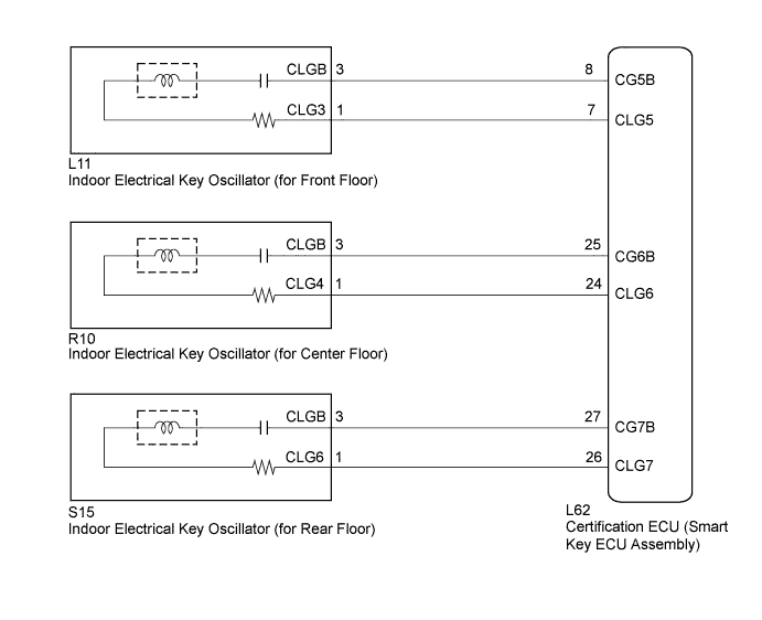
SMART KEY SYSTEM (for Entry Function) > Room Oscillator does not Recognize Key |
| 1.CHECK SMART KEY SYSTEM (for Entry Function) |
Check that entry lock and unlock functions can be operated at each door (Click here).
|
| ||||
| OK | |
 |
| 2.CHECK SMART KEY SYSTEM (for Start Function) |
Remove the battery of the key (Click here).
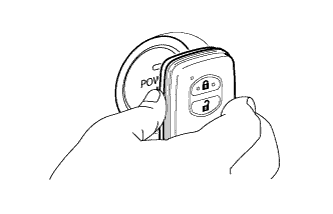 |
With the brake pedal depressed, touch the power switch while facing the logo side of the key to the power switch.
When operating the power switch, check whether the power source mode changes.
|
| ||||
| OK | |
|
| 3.CHECK WAVE ENVIRONMENT |
Install the battery to the key (Click here).
Bring the key near the indoor electrical key oscillator (for front floor), and check that the hybrid vehicle control system can be started.
Bring the key near the indoor electrical key oscillator (for center floor), and check that the hybrid vehicle control system can be started.
Bring the key near the indoor electrical key oscillator (for rear floor), and check that the hybrid vehicle control system can be started*.
*: If the customize setting for Ignition Available Area is not set All, the hybrid vehicle control system will not start. Before performing this inspection, check that All has been selected (Click here).
|
| ||||
| OK | ||
 | ||
| ||
| 4.PERFORM KEY DIAGNOSTIC MODE INSPECTION |
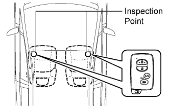 |
Diagnostic mode inspection (indoor electrical key oscillator (for front floor))
Connect the Techstream to the DLC3.
Turn the power switch on (IG).
Turn the Techstream on.
Enter the following menus: Body Electrical / Smart Key / Utility / Key Communication Check / Overhead + Front Room.
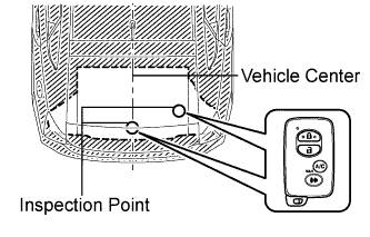
When the electrical key transmitter is in the position shown in the illustration, check that the wireless door lock buzzer sounds.
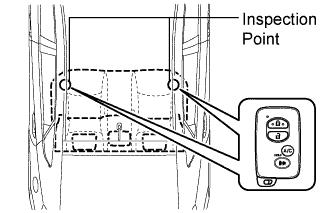 |
Diagnostic mode inspection (indoor electrical key oscillator (for center floor))
Connect the Techstream to the DLC3.
Turn the power switch on (IG).
Turn the Techstream on.
Enter the following menus: Body Electrical / Smart Key / Utility / Key Communication Check / Overhead + Rear Room.
When the electrical key transmitter is in the position shown in the illustration, check that the wireless door lock buzzer sounds.
 |
Diagnostic mode inspection (indoor electrical key oscillator (for rear floor))
Connect the Techstream to the DLC3.
Turn the power switch on (IG).
Turn the Techstream on.
Enter the following menus: Body Electrical / Smart Key / Utility / Key Communication Check / Overhead + Back Door (inside).
When the electrical key transmitter is in the position shown in the illustration, check that the wireless door lock buzzer sounds.
| Result | Proceed to |
| Wireless door lock buzzer does not sound only for indoor electrical key oscillator (for front floor). | A |
| Wireless door lock buzzer does not sound only for indoor electrical key oscillator (for center floor). | B |
| Wireless door lock buzzer does not sound only for indoor electrical key oscillator (for rear floor). | C |
| Wireless door lock buzzer sounds for all indoor electrical key oscillators. | D |
|
| ||||
|
| ||||
|
| ||||
| A | |
|
| 5.CHECK HARNESS AND CONNECTOR (CERTIFICATION ECU - INDOOR ELECTRICAL KEY OSCILLATOR) |
Disconnect the certification ECU (smart key ECU assembly) connector.
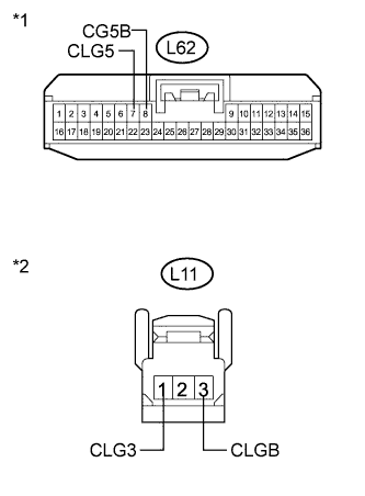 |
Disconnect the indoor electrical key oscillator (for front floor) connector.
Measure the resistance according to the value(s) in the table below.
| Tester Connection | Condition | Specified Condition |
| L62-7 (CLG5) - L11-1 (CLG3) | Always | Below 1 Ω |
| L62-8 (CG5B) - L11-3 (CLGB) | Always | Below 1 Ω |
| L62-7 (CLG5) - Body ground | Always | 10 kΩ or higher |
| L62-8 (CG5B) - Body ground | Always | 10 kΩ or higher |
| L11-1 (CLG3) - Body ground | Always | 10 kΩ or higher |
| L11-3 (CLGB) - Body ground | Always | 10 kΩ or higher |
| *1 | Front view of wire harness connector (to Certification ECU (Smart Key ECU Assembly)) |
| *2 | Front view of wire harness connector (to Indoor Electrical Key Oscillator (for Front Floor)) |
|
| ||||
| OK | |
|
| 6.INSPECT INDOOR ELECTRICAL KEY OSCILLATOR (for Front Floor (INPUT)) |
 |
Reconnect the certification ECU (smart key ECU assembly) connector.
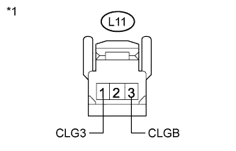
Check for pulses according to the value(s) in the table below.
| Tester Connection | Condition | Specified Condition |
| L11-1 (CLG3) - L11-3 (CLGB) |
| No pulse generation |
| L11-1 (CLG3) - L11-3 (CLGB) |
| Pulse generation |
| *1 | Front view of wire harness connector (to Indoor Electrical Key Oscillator (for Front Floor)) |
|
| ||||
| OK | |
|
| 7.REPLACE INDOOR ELECTRICAL KEY OSCILLATOR (for Front Floor) |
Replace the indoor electrical key oscillator (for front floor (Click here).
| NEXT | |
|
| 8.PERFORM KEY DIAGNOSTIC MODE INSPECTION (for Front Floor) |
Connect the Techstream to the DLC3.
Turn the power switch on (IG).
Turn the Techstream on.
Enter the following menus: Body Electrical / Smart Key / Utility / Key Communication Check / Overhead + Front Room.
|
When the electrical key transmitter is in the position shown in the illustration, check that the wireless door lock buzzer sounds.
|
| ||||
| OK | ||
| ||
| ||
| 9.CHECK HARNESS AND CONNECTOR (CERTIFICATION ECU - INDOOR ELECTRICAL KEY OSCILLATOR) |
Disconnect the certification ECU (smart key ECU assembly) connector.
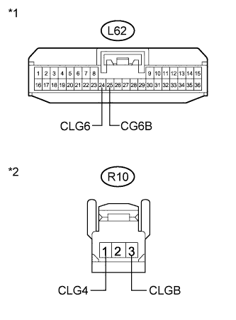 |
Disconnect the indoor electrical key oscillator (for center floor) connector.
Measure the resistance according to the value(s) in the table below.
| Tester Connection | Condition | Specified Condition |
| L62-24 (CLG6) - R10-1 (CLG4) | Always | Below 1 Ω |
| L62-25 (CG6B) - R10-3 (CLGB) | Always | Below 1 Ω |
| L62-24 (CLG6) - Body ground | Always | 10 kΩ or higher |
| L62-25 (CG6B) - Body ground | Always | 10 kΩ or higher |
| R10-1 (CLG4) - Body ground | Always | 10 kΩ or higher |
| R10-3 (CLGB) - Body ground | Always | 10 kΩ or higher |
| *1 | Front view of wire harness connector (to Certification ECU (Smart Key ECU Assembly)) |
| *2 | Front view of wire harness connector (to Indoor Electrical Key Oscillator (for Center Floor)) |
|
| ||||
| OK | |
|
| 10.INSPECT INDOOR ELECTRICAL KEY OSCILLATOR (for Center Floor (INPUT)) |
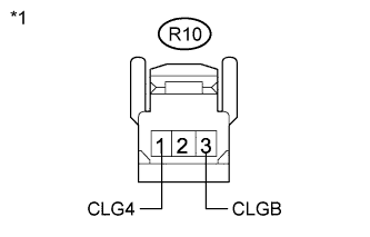 |
Reconnect the certification ECU (smart key ECU assembly) connector.
Check for pulses according to the value(s) in the table below.
| Tester Connection | Condition | Specified Condition |
| R10-1 (CLG4) - R10-3 (CLGB) |
| No pulse generation |
| R10-1 (CLG4) - R10-3 (CLGB) |
| Pulse generation |
| *1 | Front view of wire harness connector (to Indoor Electrical Key Oscillator (for Center Floor)) |
|
| ||||
| OK | |
|
| 11.REPLACE INDOOR ELECTRICAL KEY OSCILLATOR (for Center Floor) |
Replace the indoor electrical key oscillator (for center floor) (Click here).
| NEXT | |
|
| 12.PERFORM KEY DIAGNOSTIC MODE INSPECTION (for Center Floor) |
Connect the Techstream to the DLC3.
Turn the power switch on (IG).
Turn the Techstream on.
Enter the following menus: Body Electrical / Smart Key / Utility / Key Communication Check / Overhead + Rear Room.
|
When the electrical key transmitter is in the position shown in the illustration, check that the wireless door lock buzzer sounds.
|
| ||||
| OK | ||
| ||
| ||
| 13.CHECK HARNESS AND CONNECTOR (CERTIFICATION ECU - INDOOR ELECTRICAL KEY OSCILLATOR) |
Disconnect the certification ECU (smart key ECU assembly) connector.
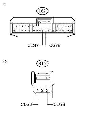 |
Disconnect the indoor electrical key oscillator (for rear floor) connector.
Measure the resistance according to the value(s) in the table below.
| Tester Connection | Condition | Specified Condition |
| L62-26 (CLG7) - S15-1 (CLG6) | Always | Below 1 Ω |
| L62-27 (CG7B) - S15-3 (CLGB) | Always | Below 1 Ω |
| L62-26 (CLG7) - Body ground | Always | 10 kΩ or higher |
| L62-27 (CG7B) - Body ground | Always | 10 kΩ or higher |
| S15-1 (CLG6) - Body ground | Always | 10 kΩ or higher |
| S15-3 (CLGB) - Body ground | Always | 10 kΩ or higher |
| *1 | Front view of wire harness connector (to Certification ECU (Smart Key ECU Assembly)) |
| *2 | Front view of wire harness connector (to Indoor Electrical Key Oscillator (for Rear Floor)) |
|
| ||||
| OK | |
|
| 14.INSPECT INDOOR ELECTRICAL KEY OSCILLATOR (for Rear Floor (INPUT)) |
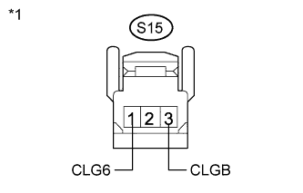 |
Reconnect the certification ECU (smart key ECU assembly) connector.
Check for pulses according to the value(s) in the table below.
| Tester Connection | Condition | Specified Condition |
| S15-1 (CLG6) - S15-3 (CLGB) |
| No pulse generation |
| S15-1 (CLG6) - S15-3 (CLGB) |
| Pulse generation |
| *1 | Front view of wire harness connector (to Indoor Electrical Key Oscillator (for Rear Floor)) |
|
| ||||
| OK | |
|
| 15.REPLACE INDOOR ELECTRICAL KEY OSCILLATOR (for Rear Floor) |
Replace the indoor electrical key oscillator (for rear floor) (Click here).
| NEXT | |
|
| 16.PERFORM KEY DIAGNOSTIC MODE INSPECTION (for Rear Floor) |
Connect the Techstream to the DLC3.
Turn the power switch on (IG).
Turn the Techstream on.
Enter the following menus: Body Electrical / Smart Key / Utility / Key Communication Check / Overhead + Back Door (inside).
|
When the electrical key transmitter is in the position shown in the illustration, check that the wireless door lock buzzer sounds.
|
| ||||
| OK | ||
| ||
| ||

