P610 HYBRID TRANSMISSION / TRANSAXLE ELECTRONIC SHIFT LEVER SYSTEM P272D19 Park Pawl Motor Circuit Current Above Threshold
DESCRIPTION
The shift control actuator assembly consists of a parking lock motor and rotation angle sensor.
The hybrid vehicle control ECU receives a P position switch signal from the P position switch (transmission shift main switch) and operates the parking lock motor through current control to engage and release the parking lock.
If the hybrid vehicle control ECU detects a malfunction in the parking lock motor system and/or ground circuit, it stores this DTC.
| DTC No. | Detection Item | DTC Detection Condition | Trouble Area | Warning Indicate | Memory |
|---|---|---|---|---|---|
| P272D19 | Park Pawl Motor Circuit Current Above Threshold | With the power switch on (IG) (IG circuit malfunction not detected), the parking lock motor current is 50 A or more or there is an open in the hybrid vehicle control ECU terminal E01 and E02 circuits for 0.1 seconds or more. | ·
Hybrid vehicle control ECU ·
Wire harness or connector |
·
Master Warning Light ·
Comes on ·
Multi-information Display Error Message ·
Displayed |
DTC stored |
CONFIRMATION DRIVING PATTERN
- HINT:
-
After repairs have been completed, clear the DTCs and then check that the vehicle has returned to normal by performing the following All Readiness check procedure.
-
Click hereDrivetrain>P610 HYBRID TRANSMISSION / TRANSAXLE>ELECTRONIC SHIFT LEVER SYSTEM>UTILITY
- 1.
Turn the power switch on (IG).
2.With the brake pedal depressed, select neutral (N).
3.Push the P position switch (transmission shift main switch).
WIRING DIAGRAM
Refer to the wiring diagram for DTC P1C8949.
Click hereDrivetrain>P610 HYBRID TRANSMISSION / TRANSAXLE>ELECTRONIC SHIFT LEVER SYSTEM>P1C8949
PROCEDURE
Disconnect the F2 hybrid vehicle control ECU connector.
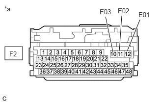
| *a | Front view of wire harness connector
(to Hybrid Vehicle Control ECU) |
Measure the resistance according to the value(s) in the table below.
- Standard Resistance (Check for Open):
Tester Connection Condition Specified Condition F2-12 (E01) - Body ground Power switch off Below 1 Ω F2-11 (E02) - Body ground Power switch off Below 1 Ω F2-10 (E03) - Body ground Power switch off Below 1 Ω
Reconnect the F2 hybrid vehicle control ECU connector.
- Result:
Proceed to OK NG
OK
NG
Click hereDrivetrain>P610 HYBRID TRANSMISSION / TRANSAXLE>ELECTRONIC SHIFT LEVER SYSTEM>P272C73
- Result:
Proceed to OK NG
OK
NG