P610 HYBRID TRANSMISSION / TRANSAXLE SHIFT LEVER REMOVAL
CAUTION / NOTICE / HINT
The necessary procedures (adjustment, calibration, initialization or registration) that must be performed after parts are removed and installed, or replaced during shift lock control unit assembly removal/installation are shown below.
| Replaced Part or Performed Procedure | Necessary Procedure | Effect/Inoperative Function when Necessary Procedure not Performed | Link |
|---|---|---|---|
|
*1: When performing learning using the GTS. Click here( |
|||
| Disconnect cable from negative auxiliary battery terminal | Memorize steering angle neutral point | Lane departure alert system (w/ Steering Control) | ( ) |
| Intelligent clearance sonar system*1 | |||
| Simple intelligent parking assist system*1 | |||
| Pre-crash safety system | |||
| Parking assist monitor system | ()
|
||
| Initialize back door lock | Power door lock control system | ()
|
|
PROCEDURE

 1. PRECAUTION
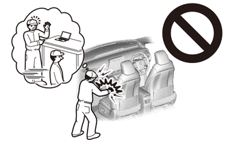
- CAUTION:
-
-
Be sure to read Precaution thoroughly before servicing.
-
Click hereVehicle Interior>SUPPLEMENTAL RESTRAINT SYSTEMS>AIRBAG SYSTEM>PRECAUTION
- NOTICE:
-
After turning the power switch off, waiting time may be required before disconnecting the cable from the negative (-) auxiliary battery terminal. Therefore, make sure to read the disconnecting the cable from the negative (-) auxiliary battery terminal notices before proceeding with work.
-
Click hereGeneral>INTRODUCTION>REPAIR INSTRUCTION>PRECAUTION
2.DISCONNECT CABLE FROM NEGATIVE AUXILIARY BATTERY TERMINAL
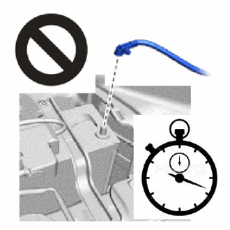
- CAUTION:
-
-
Wait at least 90 seconds after disconnecting the cable from the negative (-) auxiliary battery terminal to disable the SRS system.
- NOTICE:
-
When disconnecting the cable, some systems need to be initialized after the cable is reconnected.
-
Click hereGeneral>INTRODUCTION>REPAIR INSTRUCTION>INITIALIZATION
58910C
3.REMOVE REAR CONSOLE BOX ASSEMBLY
55436A
4.REMOVE INSTRUMENT PANEL FINISH PANEL END LH
55470
5.REMOVE INSTRUMENT CLUSTER FINISH PANEL GARNISH ASSEMBLY
67914
6.REMOVE FRONT DOOR SCUFF PLATE LH
62112
7.REMOVE COWL SIDE TRIM BOARD LH
55606
8.REMOVE NO. 1 INSTRUMENT PANEL UNDER COVER SUB-ASSEMBLY
53601
9.DISCONNECT HOOD LOCK CONTROL LEVER SUB-ASSEMBLY
55480D
10.REMOVE LOWER INSTRUMENT PANEL FINISH PANEL ASSEMBLY
73900
11.REMOVE LOWER NO. 1 INSTRUMENT PANEL AIRBAG ASSEMBLY
55406B
12.REMOVE LOWER CENTER INSTRUMENT CLUSTER FINISH PANEL SUB-ASSEMBLY
58848B
13.REMOVE SHIFT LEVER HOLE COVER
55433B
14.REMOVE NO. 2 LOWER INSTRUMENT PANEL FINISH PANEL
33560
15.REMOVE SHIFT LOCK CONTROL UNIT ASSEMBLY
Disengage the clamp.
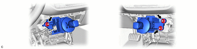
Remove the 3 nuts and separate the shift lock control unit assembly from the No. 1 instrument panel brace sub-assembly and No. 2 instrument panel brace sub-assembly.
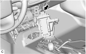
Disconnect the shift lock control unit assembly connector to remove the shift lock control unit assembly.