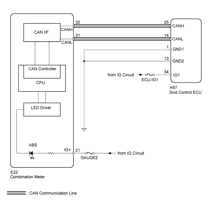
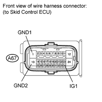
Check if the skid control ECU connector is properly installed.
OK:
The skid control ECU connector is properly installed.
NG
CONNECT CONNECTOR TO ECU SECURELY
OK
3. CHECK HARNESS AND CONNECTOR (SKID CONTROL ECU - BATTERY AND BODY GROUND)
Disconnect the skid control ECU connector.
Measure the resistance according to the value(s) in the table below.
Standard Resistance:
Tester Connection
Condition
Specified Condition
A67-1 (GND1) - Body ground
Always
Below 1 Ω
A67-13 (GND2) - Body ground
Always
Below 1 Ω
Measure the voltage according to the value(s) in the table below.
Standard Voltage:
Tester Connection
Switch Condition
Specified Condition
A67-34 (IG1) - Body ground
Ignition switch ON
11 to 14 V
NG
REPAIR OR REPLACE HARNESS OR CONNECTOR
OK
4. PERFORM ACTIVE TEST USING INTELLIGENT TESTER (ABS WARNING LIGHT)
Connect the intelligent tester to the DLC3.
Start the engine.
Select the Active Test mode on the intelligent tester (Click here).
ABS/VSC/TRC:
Tester Display
Test Part
Control Range
Diagnostic Note
ABS Warning Light
ABS warning light
Warning light ON / OFF
Observe the combination meter.
OK:
The ABS warning light is turned on or off.
HINT:
When the ABS warning light remains illuminated, an open in the wire harness of the combination meter or abnormalities in the meter circuit should be considered.
NG
CHECK METER/GAUGE SYSTEM (HOW TO PROCEED WITH TROUBLESHOOTING) (Click here)