C0210/33 Right Rear Wheel Speed Sensor Signal
Diagnostic trouble codes · Vehicles built Nov 2005 – Dec 2006
Also covers:
- C0215/34 Left Rear Wheel Speed Sensor Signal
- C1238/38 Foreign Object is Attached on Tip of Rear Speed Sensor RH
- C1239/39 Foreign Object is Attached on Tip of Rear Speed Sensor LH
- C1273/73 Low Output Signal of Rear Speed Sensor RH (Test Mode DTC)
- C1274/74 Low Output Signal of Rear Speed Sensor LH (Test Mode DTC)
- C1277/77 Abnormal Change in Output Signal of Rear Speed Sensor RH (Test Mode DTC)
- C1278/78 Abnormal Change in Output Signal of Rear Speed Sensor LH (Test Mode DTC)
Versions by build date: Nov 2005 – Dec 2006 Jan 2007 – Jul 2007 Aug 2007 – Jul 2008 from Aug 2008
DESCRIPTION
Refer to DTC C0200/31 (Click here).DTCs C1273/73, C1274/74, C1277/77 and C1278/78 can be deleted when the speed sensor sends a vehicle speed signal or the test mode ends. DTCs C1273/73, C1274/74, C1277/77 and C1278/78 are output only in the test mode.
| DTC No. |
DTC Detection Condition |
Trouble Area |
| C0210/33 C0215/34 |
When one of following conditions is met:
|
|
| C1238/38 C1239/39 |
When either condition below is met:
|
|
| C1273/73 C1274/74 |
Detected only during test mode. |
|
| C1277/77 C1278/78 |
Detected only during test mode. |
|
- HINT:
- DTC C0210/33 and C1238/38 relate to the skid control sensor RH.
- DTC C0215/34 and C1239/39 relate to the skid control sensor LH.
- DTC C0210/33 and C1238/38 relate to the skid control sensor RH.
WIRING DIAGRAM
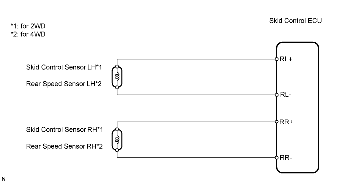

INSPECTION PROCEDURE
- NOTICE:
- Check the speed sensor signal in the test mode after cleaning or replacement (Click here).
| 1. CHECK HARNESS AND CONNECTOR (MOMENTARY INTERRUPTION) |

Using the Data List of the intelligent tester, check for any momentary interruption in the wire harness corresponding to a DTC (Click here).
Skid control ECU Item (Display)
Measurement Item / Range (Display)
Normal Condition
RR Speed Open
RR speed sensor open detection / ERROR or NORMAL
ERROR: Momentary interruption
NORMAL: Normal
RL Speed Open
RL speed sensor open detection / ERROR or NORMAL
ERROR: Momentary interruption
NORMAL: Normal
- OK:
- There are no momentary interruptions.
- HINT:
- Perform this inspection before removing the sensor and connector.
|
|
||||

| OK | |
 |
| 2. READ VALUE USING INTELLIGENT TESTER (REAR SPEED SENSOR) |
Check the Data List for proper functioning of the rear speed sensor.
Skid control ECU Item (Display)
Measurement Item / Range (Display)
Normal Condition
RR Wheel Speed
Wheel speed sensor (RR) reading: Min.: 0 km/h (0 mph), Max.: 326 km/h (202.8 mph)
Similar to speed indicated on speedometer
RL Wheel Speed
Wheel speed sensor (RL) reading: Min.: 0 km/h (0 mph), Max.: 326 km/h (202.8 mph)
Similar to speed indicated on speedometer
- OK:
- There is almost no difference between actual wheel speed and displayed speed value.
- HINT:
- There is a tolerance of +-10% in the speedometer indication.
|
|
||||

| OK | |
|
| 3. PERFORM TEST MODE INSPECTION (SIGNAL CHECK) |
Perform a test mode inspection and check for DTCs (Click here).
- OK:
- No DTCs output.
|
|
||||
| OK | |
|
| 4. RECONFIRM DTC |
Clear the DTC(s) (Click here).
Start the engine.
Drive the vehicle at a speed of 20 km/h (12 mph) or more for at least 60 seconds.
Check if the same DTC(s) is output (Click here).
Result Result
Proceed to
DTC is not output
A
DTC is output
B
|
|
||||
| A | ||
 |
||
| ||
| 5. INSPECT SKID CONTROL SENSOR OR REAR SPEED SENSOR (INSTALLATION) |
Check the speed sensor installation.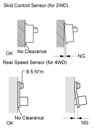
- OK:
- for 2WD
There is no clearance between the sensor and rear axle carrier.
- for 4WD
The installation bolt is tightened properly and there is no clearance between the sensor and rear axle carrier.
- Torque:
- 8.5 N*m{ 87 kgf*cm , 75 in.*lbf }
- HINT:
- Check the speed sensor signal after the replacement (Click here).
|
|
||||
| OK | |
|
| 6. CHECK SKID CONTROL SENSOR OR REAR SPEED SENSOR (TIP) |
Remove the skid control sensor (2WD) or rear speed sensor (4WD).
Check the sensor tip.
- OK:
- No scratches or foreign matter on the sensor tip.
|
|
||||
| OK | |
|
| 7. CHECK WIRE HARNESS (SKID CONTROL ECU - REAR SPEED SENSOR) |
Disconnect the A27 ECU connector.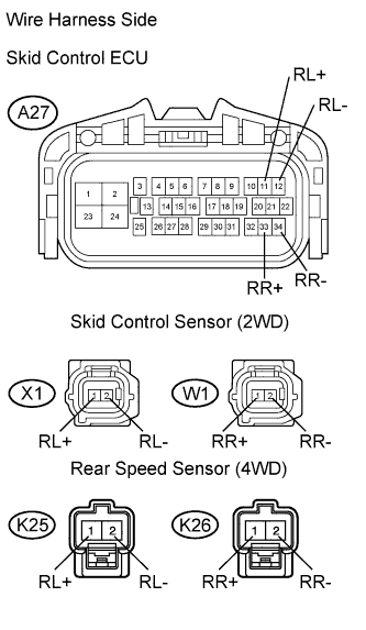
Disconnect the X1 and W1 sensor connectors for 2WD.Disconnect the K25 and K26 sensor connectors for 4WD.
Measure the resistance of the wire harness side connectors.
- Standard resistance:
- for 2WD, LH Side:
Tester Connection
Specified Condition
A27-11 (RL+) - X1-1 (RL+)
Below 1 Ω
A27-12 (RL-) - X1-2 (RL-)
Below 1 Ω
A27-11 (RL+) - Body ground
10 kΩ or higher
A27-12 (RL-) - Body ground
10 kΩ or higher
- for 2WD, RH Side:
Tester Connection
Specified Condition
A27-33 (RR+) - W1-1 (RR+)
Below 1 Ω
A27-34 (RR-) - W1-2 (RR-)
Below 1 Ω
A27-33 (RR+) - Body ground
10 kΩ or higher
A27-34 (RR-) - Body ground
10 kΩ or higher
- for 4WD, LH Side:
Tester Connection
Specified Condition
A27-11 (RL+) - K25-1 (RL+)
Below 1 Ω
A27-12 (RL-) - K25-2 (RL-)
Below 1 Ω
A27-11 (RL+) - Body ground
10 kΩ or higher
A27-12 (RL-) - Body ground
10 kΩ or higher
- for 4WD, RH Side:
Tester Connection
Specified Condition
A27-33 (RR+) - K26-1 (RR+)
Below 1 Ω
A27-34 (RR-) - K26-2 (RR-)
Below 1 Ω
A27-33 (RR+) - Body ground
10 kΩ or higher
A27-34 (RR-) - Body ground
10 kΩ or higher
|
|
||||
| OK | |
|
| 8. CHECK SKID CONTROL ECU (SENSOR INPUT VOLTAGE) |
Disconnect the X1 and W1 sensor connectors for 2WD.Disconnect the K25 and K26 sensor connectors for 4WD.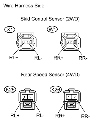
Measure the voltage of the wire harness side connectors.
- Standard voltage:
- for 2WD:
Tester Connection
Condition
Specified Condition
X1-1 (RL+) - Body ground
Ignition switch on (IG)
5.7 to 17.3 V
W1-1 (RR+) - Body ground
Ignition switch on (IG)
5.7 to 17.3 V
- for 4WD:
Tester Connection
Condition
Specified Condition
K25-1 (RL+) - Body ground
Ignition switch on (IG)
5.7 to 17.3 V
K26-1 (RR+) - Body ground
Ignition switch on (IG)
5.7 to 17.3 V
|
|
||||
| OK | |
|
| 9. RECONFIRM DTC |
Clear the DTC(s) (Click here).
Start the engine.
Drive the vehicle at a speed of 20 km/h (12 mph) or more for at least 60 seconds.
Check if the same DTC(s) is output (Click here).
Result Result
Proceed to
DTC is output
A
DTC is not output
B
|
|
||||
| A | |
|
| 10. REPLACE SKID CONTROL SENSOR OR REAR SPEED SENSOR |
Replace the skid control sensor (2WD) or rear speed sensor (4WD).
| NEXT | |
|
| 11. RECONFIRM DTC |
Clear the DTC(s) (Click here).
Start the engine.
Drive the vehicle at a speed of 20 km/h (12 mph) or more for at least 60 seconds.
Check if the same DTC(s) is output (Click here).
Result Result
Proceed to
DTC is output
A
DTC is not output
B
|
|
||||
| A | ||
|
||
| ||